Lens-barrel sliding block, focusing lens, image collecting equipment, controller and control method

A technology of focusing lens and controller, applied in the field of communication, can solve the problems of motor heating, motor gear set wear, gear set wear and other problems, and achieve the effect of improving service life

Active Publication Date: 2014-10-01
ZHEJIANG DAHUA TECH CO LTD
View PDF5 Cites 10 Cited by
  • Summary
  • Abstract
  • Description
  • Claims
  • Application Information

AI Technical Summary

Problems solved by technology

[0003] But, when the motor that the existing synchronous focus lens adopts drives the variable power lens group, after the moving variable power lens group reaches the farthest end and the nearest end of the lens structure, the structure will limit the lens group to no longer move in the same direction. If you continue to operate the motor and continue to drive in the same direction, it will cause the motor to heat up or the gear set to wear quickly, and long-term abnormal behavior will cause damage to the synchronous focus lens
[0004] The current existing synchronous focus lenses all have this problem. In the process of use, they can only estimate the range that can be traveled, and then use the motor to drive the zoom lens group to move within this range. However, there are errors and errors in this estimation method. The initial position is inaccurate. If the actual range is larger than the estimated range, the zoom range of the lens cannot be fully used. If the actual range is smaller than the estimated range, there will be multiple motor idling at the limit position each time, and the acceleration motor will heat up or the gear will The wear of the group, so it will also cause the motor to heat up or the rapid wear of the gear set, reducing the service life of the lens

Method used


Image

  • Lens-barrel sliding block, focusing lens, image collecting equipment, controller and control method
  • Lens-barrel sliding block, focusing lens, image collecting equipment, controller and control method
  • Lens-barrel sliding block, focusing lens, image collecting equipment, controller and control method

Examples


Embodiment Construction

[0030] Embodiments of the present invention provide a lens barrel slider, a synchronous focusing lens, an image acquisition device, a controller and a control method thereof.

[0031] In the embodiment of the present invention, through simple motion stroke detection, when the lens group (including the zoom lens group and the zoom lens group) reaches the limit position, the stop motor continues to run in the same direction, thereby avoiding abnormal behaviors that cause damage to the synchronous focus lens.

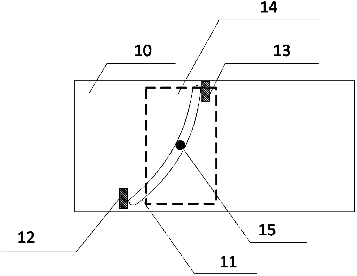
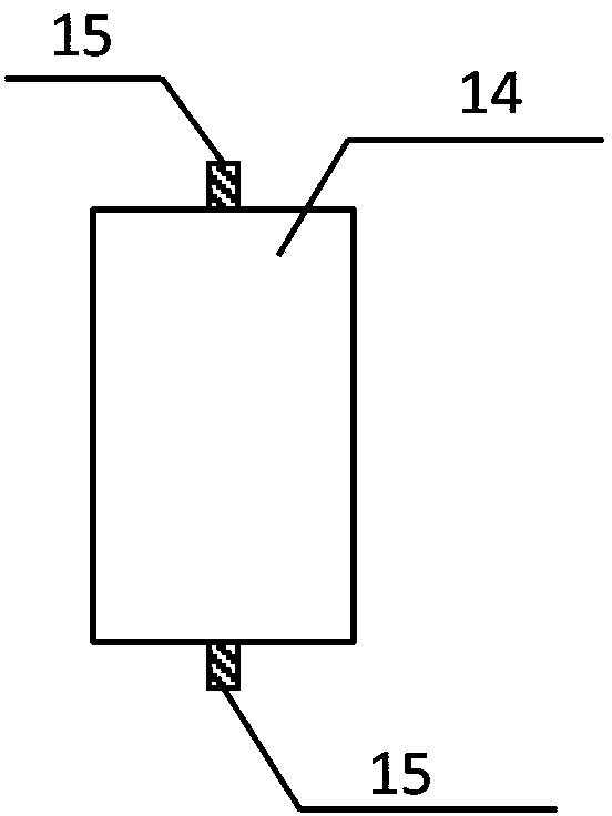
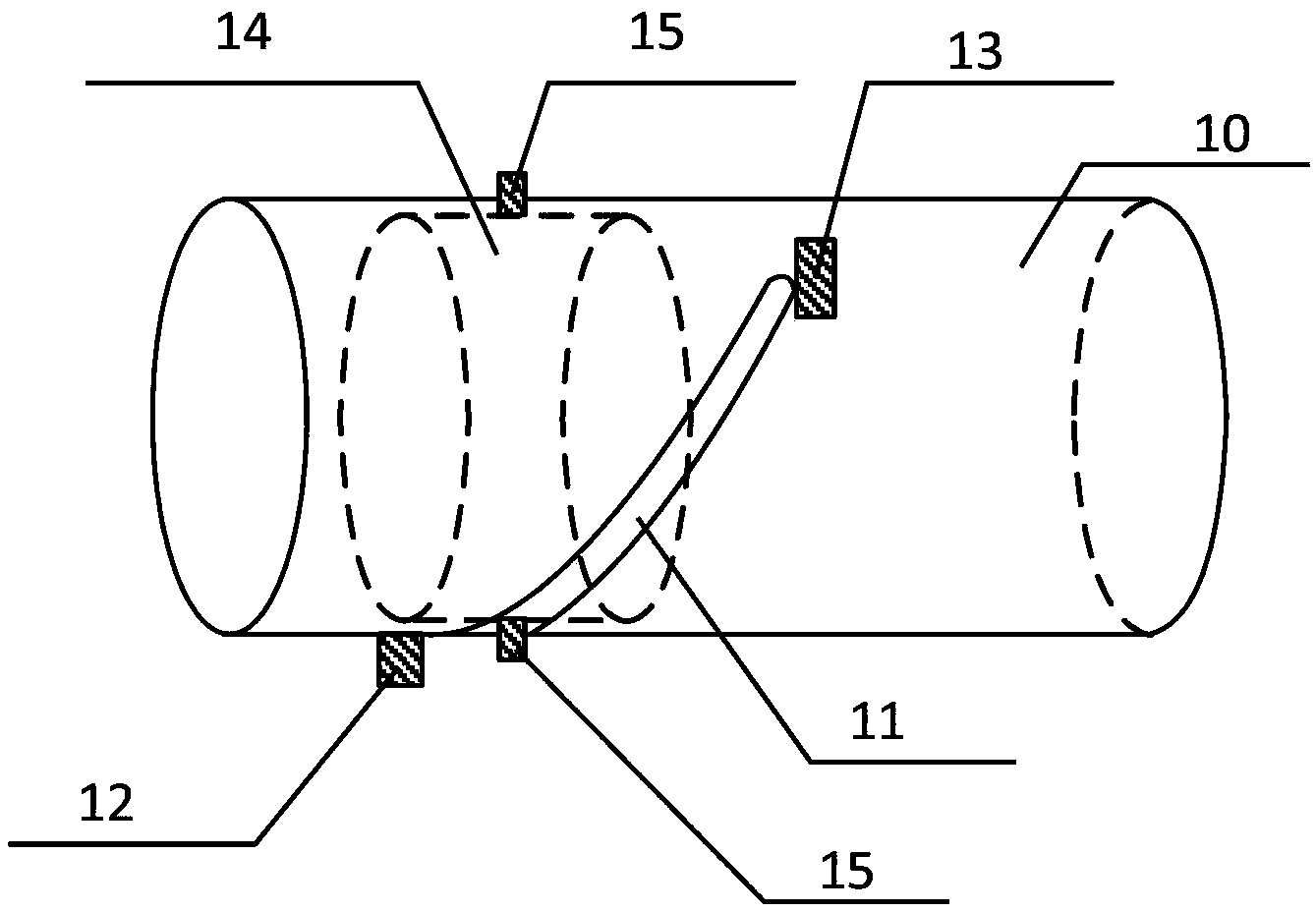
[0032] A lens barrel slider provided by an embodiment of the present invention includes a hollow cylindrical barrel, a first chute and a second chute arranged on the inner wall of the hollow cylindrical barrel, wherein the first chute is the chute of the zoom lens group , the second chute is the chute of the zoom lens group, at least one end of the first chute and / or the second chute is provided with a tact switch, wherein when the tact switch is touched, the tact switch T...


PUM


Abstract

The invention discloses a lens-barrel sliding block, a focusing lens, image collecting equipment, a controller and a control method of the controller. The control method is used for controlling a motor to stop operating towards the same direction continuously when a lens set comprising a zooming lens set and a focus variation lens set moves to a limiting position, so that the abnormal behavior of damaging the synchronous focusing lens is avoided, and the service life of the lens is prolonged. The lens-barrel sliding block comprises a hollow circular cylinder, a first sliding groove and a second sliding groove, wherein the first sliding groove and the second sliding groove are formed in the inner wall of the hollow circular cylinder. The first sliding groove is a sliding groove for the zooming lens set, and the second sliding groove is a sliding groove for the focus variation lens set. At least one end of the first sliding groove and / or the second sliding groove is provided with a touch switch. When touched, the touch switch sends out a touch signal used for indicating that the lens-barrel sliding block needs to stop driving the zooming lens set and the focus variation lens set to continue to move towards the same direction.

Description

technical field [0001] The invention relates to the field of communication technology, in particular to a lens barrel slider, a synchronous focusing lens, an image acquisition device, a controller and a control method thereof. Background technique [0002] In order to achieve zoom and zoom functions, some cameras use synchronous focusing lenses. Due to the specific optical and mechanical structure of this type of lens, the zoom lens group is driven by the associated structural parts in the process of zooming through the motor-driven zoom lens group. , synchronously realize the function of zooming and zooming. [0003] But, when the motor that the existing synchronous focus lens adopts drives the variable power lens group, after the moving variable power lens group reaches the farthest end and the nearest end of the lens structure, the structure will limit the lens group to no longer move in the same direction. If you continue to operate the motor and continue to drive in th...

Claims


Application Information

Patent Timeline
Patent Type & Authority Applications(China)
IPC IPC(8): G02B7/10G03B13/34H04N5/232
Inventor 殷俊丁洪兴张兴明傅利泉朱江明吴军吴坚
Owner ZHEJIANG DAHUA TECH CO LTD
Why Eureka
Try Eureka