Method and device for processing failure data and electronic device

A technology of fault data and electronic equipment, applied in the field of communication, can solve problems such as difficult maintenance and difficult data investigation

Active Publication Date: 2014-10-01
INVT POWER ELECTRONICS SUZHOU CO LTD
View PDF8 Cites 9 Cited by
  • Summary
  • Abstract
  • Description
  • Claims
  • Application Information

AI Technical Summary

Problems solved by technology

Since the displayed data is the data of the fault point, practice has proved that it is still difficult to troubleshoot according to the displayed data of the fault point, which causes great difficulties for maintenance

Method used


Image

  • Method and device for processing failure data and electronic device
  • Method and device for processing failure data and electronic device
  • Method and device for processing failure data and electronic device

Examples


Embodiment 1

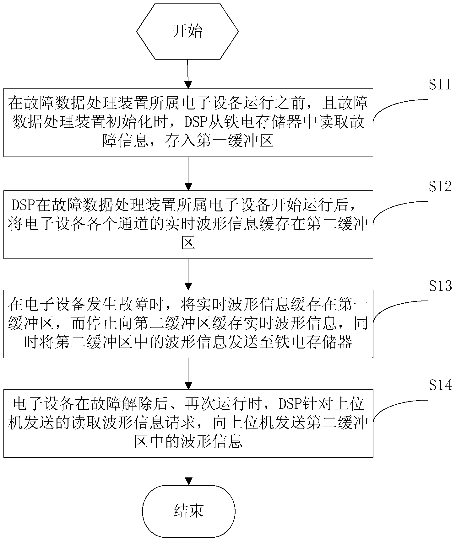
[0046] In this embodiment, the specific process of the fault data processing method provided by this application is shown. It should be noted that the fault data processing method shown in this embodiment is based on a fault data processing device, wherein the fault data processing device includes an iron Electric memory, DSP (digital signal processing, digital signal processor) and host computer.

[0047] The DSP includes a RAM, and the user can divide the RAM into multiple storage areas, such as 2, 3 or 4 storage areas, according to the user's own needs.

[0048] In this embodiment, the RAM includes two storage areas, namely a first buffer area and a second buffer area.

[0049] See figure 1 , which shows a flow chart of the fault data processing method provided by the present application, which may include the following steps:

[0050]Step S11: Before the operation of the electronic equipment to which the fault data processing device belongs and when the fault data proces...

Embodiment 2

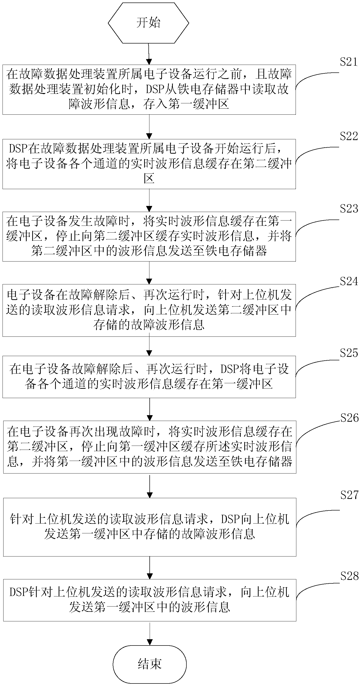
[0069] In this example, in figure 1 Another fault data processing method is extended on the basis of the fault data processing method shown, please refer to figure 2 , which shows another flow chart of the fault data processing method provided by the present application, which may include the following steps:

[0070] Step S21: Before the operation of the electronic equipment to which the fault data processing device belongs and when the fault data processing device is initialized, the DSP reads fault waveform information from the ferroelectric memory and stores it in the first buffer.

[0071] Step S22: DSP caches the real-time waveform information of each channel of the electronic equipment in the second buffer after the electronic equipment to which the faulty data processing device belongs starts running.

[0072] Step S23: When the electronic device fails, the DSP buffers the real-time waveform information in the first buffer, stops buffering the real-time waveform info...

Embodiment 3

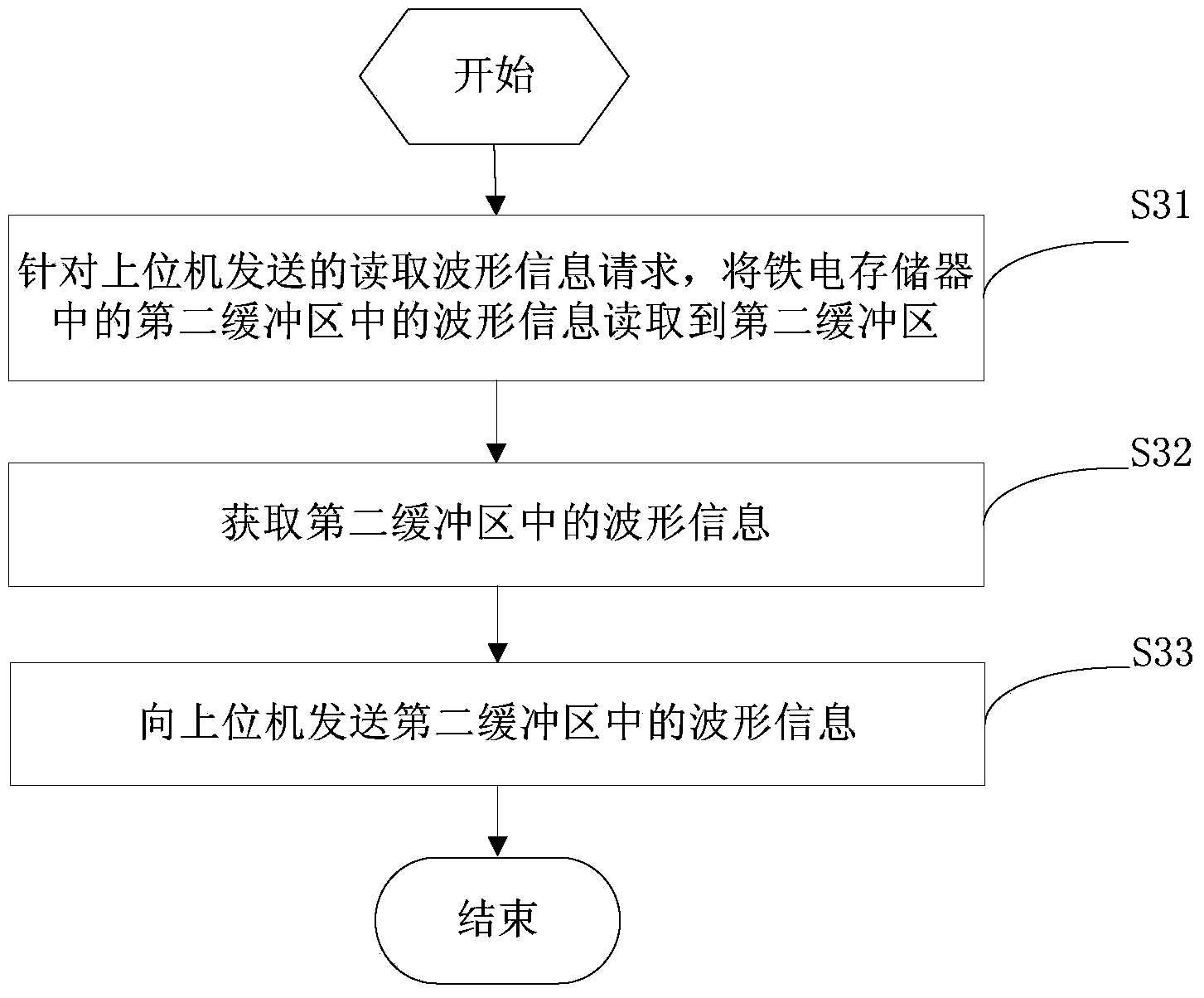
[0089] In this embodiment, it shows the specific process of sending the waveform information in the second buffer to the host computer in response to the request for reading waveform information sent by the host computer in Embodiment 1, please refer to image 3 , image 3 It shows a sub-flow chart of the fault data processing method provided by the present application. The specific process of the DSP sending the waveform information of the second buffer to the host computer for the read waveform information request sent by the host computer may include The following steps:

[0090] Step S31: For the read waveform information request sent by the host computer, the DSP reads the waveform information in the second buffer in the ferroelectric memory to the second buffer.

[0091] Step S32: Obtain the waveform information in the second buffer.

[0092] Step S33: sending the waveform information in the second buffer to the host computer.

[0093] In this embodiment, the specific p...


PUM


Abstract

The invention provides a method and a device for processing failure data and an electronic device. The method is based on the device for processing failure data; the device for processing failure data comprises a ferroelectric memory, a digital signal processor (DSP) and an upper computer. When the electronic device of the device for processing failure data is out of order, real-time waveform information is cached in a first buffer region and stopped from being cached to a second buffer region, and the waveform information in the second buffer region is sent to the ferroelectric memory; the waveform information in the second buffer region is sent to the upper computer upon a waveform information reading request sent by the upper computer; as the waveform information in the second buffer region is failure point waveform information and waveform information before a failure point, the device for processing failure data is capable of displaying either the failure point waveform information or the waveform information before the failure point, and therefore, the state of data change before a failure can be visually represented so that the failure can be found conveniently, and moreover, the difficulty of overhauling is reduced.

Description

technical field [0001] The present application relates to the communication field, in particular to a fault data processing method, device and electronic equipment. Background technique [0002] Due to the complex working environment of electronic equipment such as frequency converters, when various failures (such as sudden power failure) occur in electronic equipment such as frequency converters, relevant staff may not be able to see them in time. Even if the equipment fails in time, it cannot be determined to cause the failure s reason. [0003] In order to solve the problem that the cause of the failure cannot be determined after the equipment is found to be faulty, the current common method is to store the data of the fault point in the ferroelectric memory, read it from the ferroelectric memory into the RAM when the power is turned on, and then perform show. Since the displayed data is the data of the fault point, practice has proved that it is still difficult to trou...

Claims


Application Information

Patent Timeline
Patent Type & Authority Applications(China)
IPC IPC(8): G06F11/22
Inventor 狄鹏王辉华
Owner INVT POWER ELECTRONICS SUZHOU CO LTD
Why Eureka
Try Eureka