
Solar charger integrated with load output control

A solar charger, load output technology, applied in current collectors, output power conversion devices, control/regulation systems, etc., can solve the problems of users who are not informed in time, difficult to start smoothly, and battery overcharged.

Pending Publication Date: 2022-07-22
ZHEJIANG TTN ELECTRIC
View PDF0 Cites 0 Cited by
  • Summary
  • Abstract
  • Description
  • Claims
  • Application Information

AI Technical Summary

Problems solved by technology

[0003] 1. Since the output voltage of the solar battery charger itself is relatively unstable, it is not easy to start up smoothly under the condition of very low voltage; under the condition of high voltage, the circuit cannot be guaranteed to withstand high voltage shock
The system itself has poor working voltage stability and poor security
[0004] 2. When the battery is charging, it cannot be connected to the load (such as electric fan, mobile phone computer charging, etc.) to work, which will easily cause a large amount of energy loss
If no load is connected, because the safe charging current of the battery is relatively small, during the charging process, if the charging voltage is too high, the current will increase accordingly, and the heat generation of the battery electrodes will also increase; at the same time, due to the solar panel The power is large, when the charging voltage reaches the maximum voltage of the battery, it will switch to a constant voltage charging state, so that the solar panel will not work at the maximum power point, resulting in a certain energy loss
[0005] 3. When the voltage of the solar panel is lower than the voltage of the battery, especially at night or in rainy days, the electric energy of the battery will flow to the solar panel, causing power loss or even damage to the solar panel, so that the solar panel is not effectively protected
[0006] 4. During the charging process of the existing solar charger, it cannot be monitored at all times. When the battery is fully charged, the user will know that it is not timely
If the battery is fully charged and is still being charged, it may cause the battery to be overcharged or even damage the battery

Method used


Image

  • Solar charger integrated with load output control
  • Solar charger integrated with load output control
  • Solar charger integrated with load output control

Examples


Embodiment Construction

[0029] The present invention will be further described in detail below in conjunction with the accompanying drawings and embodiments.

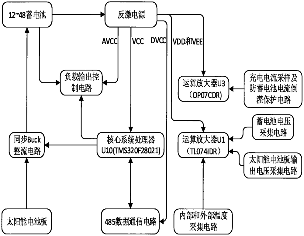
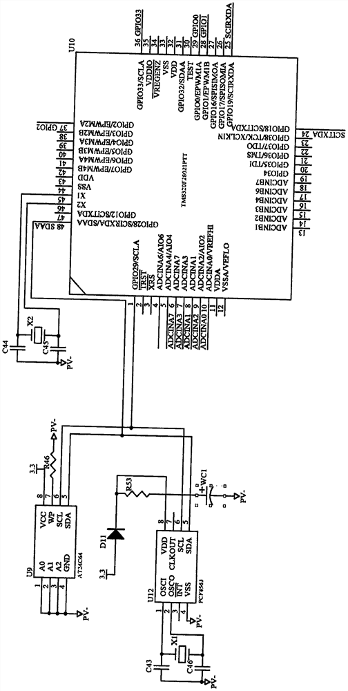
[0030] like figure 1As shown, this embodiment includes a battery, a solar panel, a flyback power supply based on the UC2845 control chip U4, a processor U10 with the chip model TMS320F28021, a synchronous Buck rectifier circuit based on the IR2110S driver chip U8, and a load output control circuit. circuit, 485 data communication circuit, charging current sampling circuit, battery voltage sampling circuit and solar panel output voltage sampling circuit, wherein:

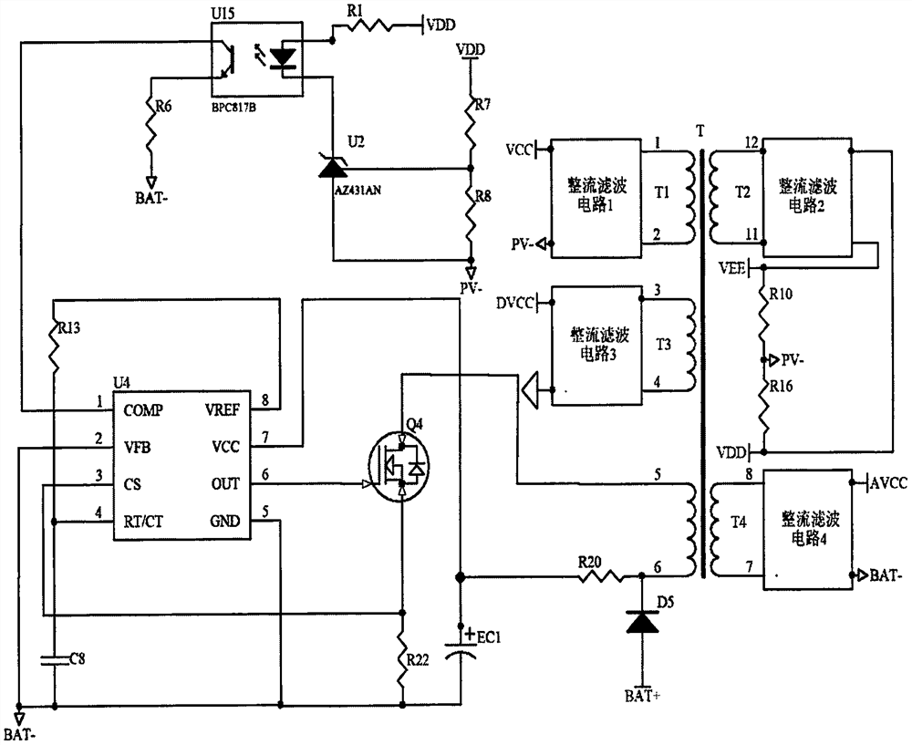
[0031] (1) If figure 2 As shown, the power input terminal of the flyback power supply is connected to the output terminal of the battery, and the output terminals of the flyback power supply respectively output the analog power supply voltage AVCC, the digital circuit power supply voltage VCC, the positive digital power supply voltage DVCC and the positive and Negative power suppl...


PUM


Abstract

The invention relates to a solar battery charger, in particular to a solar charger integrated with load output control. The system comprises a storage battery, a solar cell panel, a synchronous Buck rectification circuit, a processor, a flyback power supply and a load output control circuit, the flyback power supply provides multiple isolation voltages for a chip and a circuit, and the control end of the synchronous Buck rectification circuit is connected with the first output end of the processor; the control end of the load output control circuit is connected with the second output end of the processor. The invention aims to design a solar charger integrated with load output control, which can automatically drive other loads to work while charging a battery, reduces electric energy loss, and has the advantages of stable system work and good safety. Compared with the prior art, the system has the advantages of being good in working stability, capable of remotely monitoring the charging state of the battery, capable of effectively protecting the solar cell panel and the storage battery, reliable in operation data storage and the like.

Description

technical field [0001] The invention relates to a solar battery charger, in particular to a solar charger with integrated load output control. Background technique [0002] The solar battery charger uses solar energy as the energy source, converts the light energy into electrical energy and stores it in the battery through the control circuit. At present, solar battery chargers include solar panels, batteries, synchronous Buck rectifier circuits, charging current sampling circuits, battery voltage sampling circuits and solar panel output voltage sampling circuits. The shortcomings are as follows: [0003] 1. Because the output voltage of the solar battery charger itself is relatively unstable, it is not easy to start smoothly when the voltage is very low; in the case of high voltage, the circuit cannot be guaranteed to withstand high voltage shocks. The working voltage of the system itself is not stable, and the safety is also poor. [0004] 2. When the battery is charging...

Claims


Application Information

Patent Timeline
IPC IPC(8): H02J7/35H02J7/00H02H11/00H02M3/158H02M1/092
CPCH02J7/35H02J7/0063H02J7/0047H02J7/0029H02H11/00H02M3/1582H02M1/092
Inventor 滕敏亮江先志李明华潜卫强金建广赖臣章
Owner ZHEJIANG TTN ELECTRIC
Learn More