Component mounting method

An installation method and component technology, which is applied in the direction of electrical components, electrical components, electric solid devices, etc., can solve the problems of control processing control load increase, etc.

Inactive Publication Date: 2014-10-01
PANASONIC CORP
View PDF2 Cites 16 Cited by
  • Summary
  • Abstract
  • Description
  • Claims
  • Application Information

AI Technical Summary

Problems solved by technology

Therefore, the control process for the rotational positioning of each component becomes complicated, and the control load increases. In addition, the reciprocating rotation operatio

Method used


Image

  • Component mounting method
  • Component mounting method
  • Component mounting method

Examples


Example Embodiment

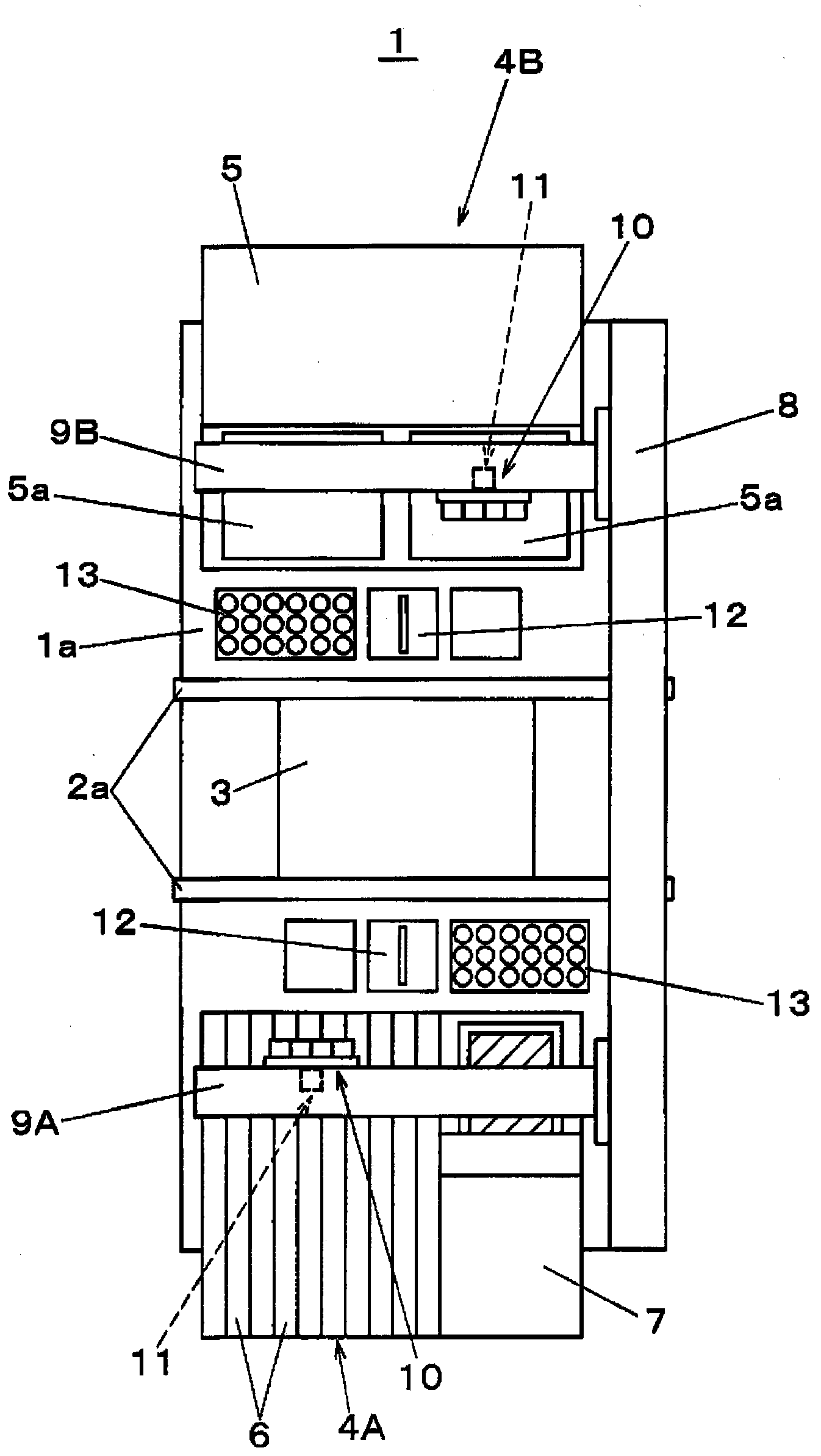
[0030] Next, embodiments of the present invention will be described with reference to the drawings. First, refer to figure 1 , figure 2 The structure of the electronic component mounting apparatus will be described. exist figure 1 Among them, on the base 1 a of the electronic component mounting apparatus 1 , the board conveyance mechanism 2 is arranged along the X direction (the board conveyance direction). The board conveyance mechanism 2 conveys the board 3 which is the object of the component mounting operation. Component supply parts for supplying electronic components are arranged on both sides of the substrate transfer mechanism 2 , and a plurality of tape feeders 6 for supplying electronic components held on a tape and a plurality of tape feeders for passing the electronic components on one side of the component supply part 4A are arranged. Transfer Paste transfer unit 7 for transferring paste such as flux onto electronic components is detachably mounted in paralle...


PUM


Abstract

The invention provides a component mounting method which can suppress an error generated by tooth gap through simpler controlling in rotating positioning of the component. Before an attracting nozzle (25) which attracts an electronic component (P) is photographed from lower part and component identification is performed on the attracted electronic component (P), the attracting nozzle (25) is rotated for a preset angle deltatheta around an axially counterclockwise direction (first rotating direction) of the attracting nozzle, so that the central line (CL) of the electronic component (P) is arranged at a position which offsets to the couterclockwise direction than a direction reference line (BL). Furthermore a detection result is offset based on the component rotation direction which is detected through component identification, so that the attracting nozzle (25) always rotate around the axially clockwise direction (second rotating direction) of the attracting nozzle, thereby positioning the rotating position of the electronic component (P) to a preset mounting angle.

Description

technical field [0001] The present invention relates to a component mounting method for mounting components on a substrate. Background technique [0002] In the component mounting operation of the component mounting device that mounts electronic components on the board, when the components taken out from the component supply unit are transferred and mounted on the mounting point of the board, the components are positioned in the X and Y directions with respect to the mounting point, and , the rotational position of the component in the plane needs to be positioned correctly and consistent with the mounting angle specified for each mounting point. This rotational positioning is performed by a θ rotation operation that rotates the suction nozzle holding the component around the suction nozzle axis. In this θ rotation operation, in order to minimize the required rotation amount until it matches the correct installation angle, the rotation direction of the suction nozzle is sel...

Claims


Application Information

Patent Timeline
IPC IPC(8): H05K13/04
CPCH01L2924/181
Inventor 东雅之
Owner PANASONIC CORP
Why Eureka
Try Eureka