Robot, robot system, control apparatus, and control method

Inactive Publication Date: 2016-07-06
SEIKO EPSON CORP
View PDF6 Cites 17 Cited by
  • Summary
  • Abstract
  • Description
  • Claims
  • Application Information

AI Technical Summary

Problems solved by technology

[0010] However, in the methods described in Patent Document 1 and Non-Patent Document 1, when correcting the manipulator by manual operation, it is necessary to stop the operation of each actuator and change the posture of the manipulator by manual work. takes time and labor
In addition, when the robot is calibrated by driving each actuator, since the calibration of the robot has not been completed, the robot cannot be operated correctly, and the actuators and components constituting the robot cannot be energized while the TCP is bound. It is very difficult to control the manipulator when the load is applied
In addition, in order to constrain the manipulator structurally with certain jigs, a large-scale jig that can withstand the operating load of the manipulator is required, so there is a problem that the installation position of the jig is corrected and portability is impaired.
[0011] In addition, in the robot described in Patent Document 2, if both the first robot and the second robot are not properly calibrated, the work of both the first robot and the second robot cannot be performed correctly.

Method used


Image

  • Robot, robot system, control apparatus, and control method
  • Robot, robot system, control apparatus, and control method
  • Robot, robot system, control apparatus, and control method

Examples


no. 1 approach

[0087] Hereinafter, a first embodiment of the present invention will be described with reference to the drawings.

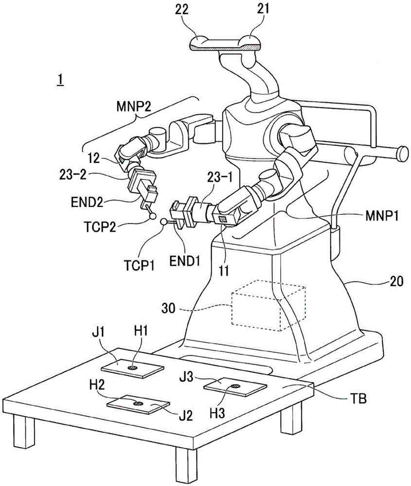
[0088] figure 1 It is a configuration diagram showing an example of the robot system 1 of the present embodiment.

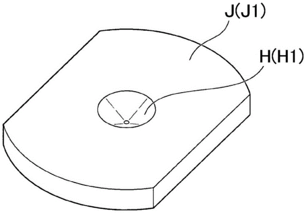
[0089] The robot system 1 includes a robot 20 and a control device 30 . The robot system 1 calibrates the manipulator included in the robot 20 using a plurality of jigs. In this example, robot system 1 is using figure 1 Three jigs J1 to J3 are shown as the configuration of the above-mentioned plurality of jigs, but a configuration using four or more jigs is also possible. Hereinafter, as long as the jigs J1 to J3 are not distinguished and described, they will be collectively referred to as jig J and described.

[0090]Here, calibration of the manipulator performed by the robot system 1 will be described. The robot system 1 acquires information indicating the rotation angle of each of the plurality of actuators included in the manipulator of the...

no. 2 approach

[0211] Hereinafter, a second embodiment of the present invention will be described with reference to the drawings.

[0212] Figure 10 It is a configuration diagram showing an example of the robot system 2 of the present embodiment. In addition, in 2nd Embodiment, the same code|symbol is attached|subjected to the same component part as 1st Embodiment, and description is abbreviate|omitted.

[0213] The robot system 2 includes a robot 20 and a control device 30 . Robot System 2 uses Figure 10 The illustrated jig J1 calibrates the manipulator included in the robot 20 . Here, calibration of the manipulator performed by the robot system 2 will be described. The robot system 2 acquires information indicating the rotation angle of each of the plurality of actuators included in the manipulator of the robot 20 from an encoder connected to (or provided with) each actuator. Hereinafter, for convenience of description, the rotation angle of the actuator may be simply referred to as...

no. 3 approach

[0275] Hereinafter, a third embodiment of the present invention will be described with reference to the drawings.

[0276] Figure 12 It is a configuration diagram showing an example of the robot system 3 of the present embodiment.

[0277] The robot system 3 of the third embodiment includes a robot 20a and a control device 30a. In addition, in the third embodiment, the same reference numerals are assigned to the same components as those in the second embodiment, and description thereof will be omitted.

[0278] The robot system 3 calibrates the first manipulator MNP1 and the second manipulator MNP2 by the method described in the second embodiment, and then causes the robot 20a to rearrange the work object M placed on the upper surface of the work table TB. Jobs at specified locations. Hereinafter, this operation will be referred to as a predetermined operation and will be described. When performing this predetermined work, in the robot system 3, the rotation angle of the ...


PUM


Abstract

The invention provides a robot, a robot system, a control apparatus and a control method. In order to provide the robot which easily calibrates a manipulator, a robot includes an arm and a force sensor, in which the arm is calibrated by causing the arm to take a plurality of attitudes on the basis of an output value from at least the force sensor in a state in which a part of a first member attached to a tip of the arm is moved so that a distance between the part and a second member becomes a distance of 1 for each of a plurality of second members, the part being provided at a position which is not present on a rotation axis of the tip of the arm.

Description

technical field [0001] The present invention relates to a robot, a robot system, a control device and a control method. Background technique [0002] In order to make robots perform high-precision work, research and development have been carried out on the calibration of robot mechanisms, imaging devices, and work environments. [0003] In this regard, there is known a TCP (Tool Center Point Tool Center Point) in which the manipulator is constrained structurally by some jig without using an external measuring device, or a method of calibrating the manipulator by connecting the manipulators (for example, refer to Patent Document 1. Non-Patent Document 1). [0004] The position of the TCP moving along with the driving of the manipulator can be calculated based on forward kinematics by assigning a rotation angle to each of a plurality of actuators included in the manipulator. However, the actual position of the TCP reached when these actuators are driven to realize the given ...

Claims


Application Information

Patent Timeline
Patent Type & Authority Applications(China)
IPC IPC(8): B25J9/00B25J9/16
CPCB25J9/0048B25J9/1602B25J9/1694B25J9/0087B25J13/085B25J19/023G05B2219/39024G05B2219/40298B25J9/1692Y10S901/09
Inventor 石毛太郎平林友一降旗郁马
Owner SEIKO EPSON CORP
Why Eureka
Try Eureka