Automatic injector

A technology for syringes and injection devices, which is applied in the direction of automatic injectors, syringes, ampoule syringes, etc., and can solve the problems of injection force/button extension reduction, etc.

Active Publication Date: 2014-10-01
SANOFI SA
View PDF4 Cites 28 Cited by
  • Summary
  • Abstract
  • Description
  • Claims
  • Application Information

AI Technical Summary

Problems solved by technology

Injection force / button extension, hand jitter and likelihood of delivering an incomplete dose are reduced

Method used


Image

  • Automatic injector
  • Automatic injector
  • Automatic injector

Examples


Embodiment Construction

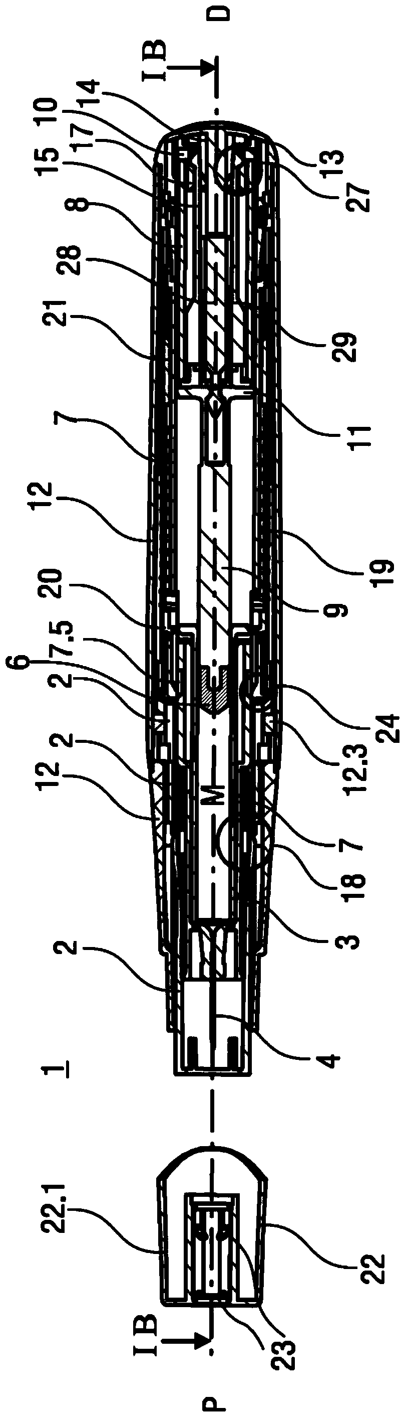
[0052]The term "bevel joint" in this specification is a joint between two parts at least one of which has a bevel that engages the other so that when the two parts are pushed against each other in the axial direction One of the two parts bends sideways when facing each other, assuming that this part is not prevented from bending sideways.

[0053] Figure 1A with 1B Two longitudinal sections of the autoinjector 1 are shown in different sections rotated by approximately 90° relative to each other, the autoinjector 1 being in the starting state before the start of the injection. The autoinjector 1 includes a housing 2 . In the following, the frame 2 is generally considered to be fixed in position, so the movements of other components are described relative to the frame 2 . A syringe 3 with a hollow injection needle 4 , for example a Hypak syringe, is arranged in a proximal-side portion of the autoinjector 1 . A needle guard (not shown) is attached to the needle 4 when the aut...


PUM


Abstract

Described is an injection device for administering a dose of a medicament comprising a case having a proximal end and a distal end, a carrier adapted to accommodate a syringe, and a trigger button. In a first state, the trigger button is coupled to the case and / or the carrier and abuts the distal end of the case. In an intermediate state, the case moves proximally relative to the carrier and the trigger button, and the trigger button engages the carrier. In a second state, the trigger button and the carrier move proximally relative to the case, and the trigger button disengages the carrier and engages the case.

Description

technical field [0001] The present invention relates to autoinjectors for delivering doses of medicaments. Background technique [0002] Administering injections presents many risks and challenges, both psychologically and physically, for both users and healthcare professionals. [0003] Injection devices (ie devices capable of delivering medicament from a medicament container) are generally divided into two types - manual devices and auto-injectors. [0004] In manual devices, the user must provide mechanical energy to drive fluid through the needle. This is typically done with some form of button / plunger which the user must continuously depress during the injection. This solution has many drawbacks for the user. If the user stops pressing the button / plunger, the injection will also stop. This means that if the device is not being used properly (ie the plunger is not fully depressed to its end position), the user will deliver an insufficient dose. The injection force m...

Claims


Application Information

Patent Timeline
Patent Type & Authority Applications(China)
IPC IPC(8): A61M5/20A61M5/28
CPCA61M2005/208A61M5/326A61M2205/582A61M5/2033A61M5/3204A61M2205/581A61M5/3157A61M2205/583A61M2005/206
Inventor S.F.布里尔顿T.坎普
Owner SANOFI SA
Why Eureka
Try Eureka