Spatially Masked Update for Electronic Paper Displays

a technology of electronic paper displays and update rates, applied in the field of electronic paper displays, can solve the problems of slow update rate, less accurate gray level control, and lower color resolution

Active Publication Date: 2008-12-18
E INK CORPORATION
View PDF96 Cites 31 Cited by
  • Summary
  • Abstract
  • Description
  • Claims
  • Application Information

AI Technical Summary

Benefits of technology

[0019]One embodiment of a system for updating an image on a bi-stable display includes a module for determining a final optical state, estimating a current optical state and determining a desired intermediate state o...

Problems solved by technology

A comparison of EPDs to Cathode Ray Tube (CRT) displays or Liquid Crystal Displays (LCDs) reveals that in general, EPDs require much less power and have higher spatial resolution, but have the disadvantages of slower update rates, less accurate gray level control, and lower color resolution.
Color devices are becoming available often through the addition of a color filter, which tends to reduce the spatial resolution and the contrast.
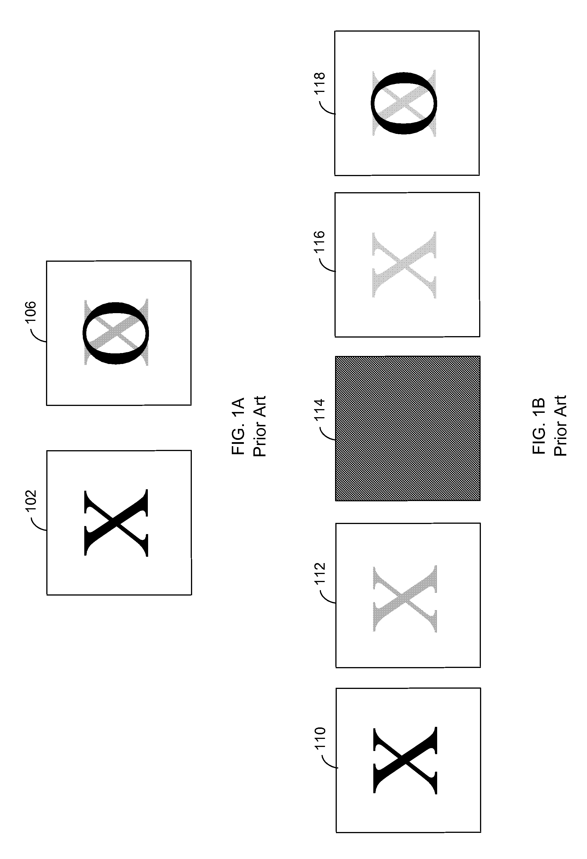
While electronic paper displays have many benefits there are two problems: (1) slow update speed (also called update latency); and (2) visibility of previously displayed images, called ghosting.
The first problem is that most EPD technologies require a relatively long time to update the image as compared with conventional CRT or LCD displays.
A typical LCD takes approximately 5 milliseconds to change to the correct value, supporting frame rates of up to 200 frames per second (the achievable frame rate is typically limited by the ability of the display driver electronics to modify all the pixels in the display).
While this update time is certainly sufficient for the page turning needed by electronic books, it is problematic for interactive applications like pen tracking, user interfaces and the display of video.
This fluid also restricts the particle movement when an electric field is applied and causes the display to be very slow to upd...

Method used


Image

  • Spatially Masked Update for Electronic Paper Displays
  • Spatially Masked Update for Electronic Paper Displays
  • Spatially Masked Update for Electronic Paper Displays

Examples


Embodiment Construction

[0032]The Figures (FIGS.) and the following description relate to preferred embodiments by way of illustration only. It should be noted that from the following discussion, alternative embodiments of the structures and methods disclosed herein will be readily recognized as viable alternatives that may be employed without departing from the principles of what is claimed.

[0033]As used herein any reference to “one embodiment,”“an embodiment,” or “some embodiments” means that a particular element, feature, structure, or characteristic described in connection with the embodiment is included in at least one embodiment. The appearances of the phrase “in one embodiment” in various places in the specification are not necessarily all referring to the same embodiment.

[0034]Some embodiments may be described using the expression “coupled” and “connected” along with their derivatives. It should be understood that these terms are not intended as synonyms for each other. For example, some embodiment...


PUM


Abstract

Electronic Paper Displays can suffer from “ghosting” or previous images remaining partially visible after the display has updated to show a new image. A pseudo-random noise intermediate image is used to make the ghosting less visible to human observers. Further, other intermediate images can be used to convey visible information or to convey secret information, e.g. a watermark. A control signal for driving the bi-stable display from the current optical state to an intermediate state, then to a final optical state is also determined. In some embodiments, the intermediate state for each pixel is determined in a pseudo-random manner. The pseudo-random noise values are applied to the bi-stable display to remove noise and other artifacts from the end resulting images. The determined control signal is applied to the bi-stable display to drive the bi-stable to the intermediate state, then to the final optical state.

Description

CROSS REFERENCE TO RELATED APPLICATIONS[0001]This application claims the benefit of U.S. Provisional Patent Application No. 60 / 944,415, filed Jun. 15, 2007, entitled “Systems and Methods for Improving the Display Characteristics of Electronic Paper Displays,” the contents of which are hereby incorporated by reference in its entirety.BACKGROUND[0002]1. Field of Art[0003]The disclosure generally relates to the field of electronic paper displays. More particularly, the invention relates to reducing visual artifacts on bi-stable displays.[0004]2. Description of the Related Art[0005]Several technologies have been introduced recently that provide some of the properties of paper in a display that can be updated electronically. Some of the desirable properties of paper that this type of display tries to achieve include: flexibility, wide viewing angle, low cost, light weight, low power consumption, high resolution, high contrast and readability indoors and outdoors. Because these displays a...

Claims


Application Information

Patent Timeline
IPC IPC(8): G09G3/38
CPCG02F1/167G09G3/3433G09G3/344G09G2300/0473G09G2320/0247G09G2320/0252G09G2320/0257G09G2360/18G09G2380/02G09G3/035
Inventor GORMISH, MICHAEL J.FENG, GUOTONG
Owner E INK CORPORATION
Why Eureka
Try Eureka