

Image display apparatus
a technology of display apparatus and display light, which is applied in the direction of projectors, instruments, optics, etc., can solve the problems of degrading the visibility of display light, and achieve the effect of high visibility
- Summary
- Abstract
- Description
- Claims
- Application Information
AI Technical Summary
Benefits of technology
Problems solved by technology
Method used
Image

Examples
first modification
(First Modification)
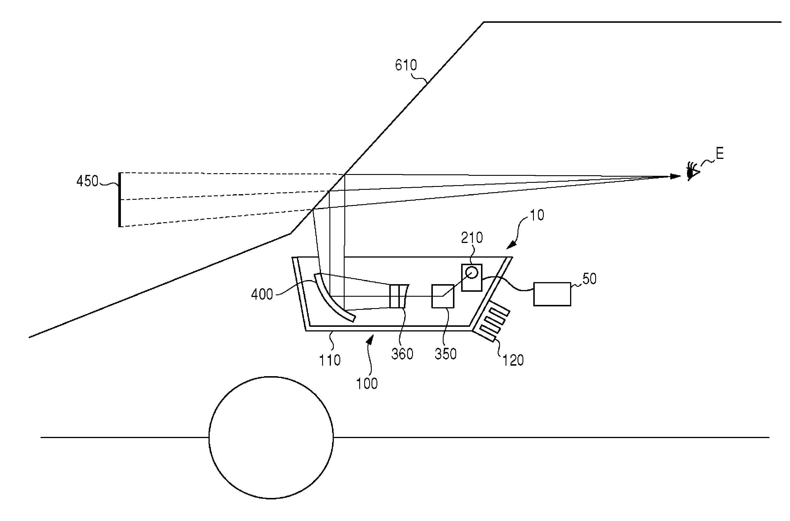
[0056]FIG. 7 shows an intermediate image forming unit 360 according to a first modification. In the first modification, a transmission-type screen, where diffusion beads 367 are provided on a first main surface 366a of a base member 366, is used as the diffusing screen 362. In this configuration, the image display light is made to enter a first main surface 366a side where the diffusion beads 367 are provided, so that the direction of the chief ray of the image display light is controlled in the diffusing screen 362 as well.
[0057]The diffusing screen 362 has the base member 366 and a plurality of diffusion beads 367. The base member 366 is a flat plate constituted by a transparent resin material or the like, and has a first main surface 366a and a second main surface 366b that face each other. The diffusion beads 367 are highly transparent beads suitable for optical use, and the diameter of each bead is 10 micrometers or less. The diffusion beads 367 are applied ...
second modification
(Second Modification)
[0061]FIG. 9 shows an intermediate image forming unit 360 according to a second modification. In the second modification, a microlens array 368 is used in substitution for the diffusing screen 362, and a Fresnel lens 369 is used as the concave lens 364. The microlens array 368 and the Fresnel lens 369 are formed integrally with each other. The microlens array is formed on a first surface 360a of the intermediate image forming unit 360, whereas the Fresnel lens is formed on a second surface 360b thereof. In this configuration, the Fresnel lens 369 controls the direction of the chief ray of the image display light, and the microlens array 368 controls the distribution angle of the image display light.
[0062]In a modification to the second modification, the diffusing screen 362 or the concave lens 364 described in the above embodiments may be combined with the microlens array 368 or the Fresnel lens 369. For example, the concave lens 364 may be used as the means for...
third modification
(Third Modification)
[0063]In the above-described embodiments and modifications, an exemplary configurations is shown where the concave lens 364 is arranged in front of the diffusing screen 362 as the intermediate image forming unit 360, namely where the image display light having passed through the concave lens 364 enters the diffusing screen 362. In still another modification, the order in which the diffusing screen 362 and the concave lens 364 are arranged may be reversed. In such a case, optical elements are arranged in the order of the intermediate mirror 350, the diffusing screen 362, the concave lens 364 and the projection mirror 400 between the intermediate mirror 350 and the projection mirror 400. Even though the direction of the intermediate image forming unit 360 is reversed, the diffusing screen 362 controls the distribution angle of the image display light, and the concave lens 364 controls the direction of the chief thereof, so that a highly visible virtual image 450 ca...
PUM
 Abstract
Description
Claims
Application Information