Catoptric reduction projection optical system and exposure apparatus and method using same

a reduction projection and optical system technology, applied in the field of photolithography, can solve the problems of inability to construct a reduction projection optical system as a dioptric optical system or a catoptric optical system, limited practical use of optical glass, and inability to use optical glass materials, etc., to achieve the effect of improving the imaging performance of an actual manufactured system and excellent imaging performan

Inactive Publication Date: 2001-04-10
NIKON CORP
View PDF4 Cites 93 Cited by
  • Summary
  • Abstract
  • Description
  • Claims
  • Application Information

AI Technical Summary

Benefits of technology

Accordingly, the present invention has the objective to achieve extremely excellent imaging performance while keeping the number of reflective surfaces to a relatively small number, and has a further objective to improve the imaging performance of an actually manufactured system.

Problems solved by technology

Nevertheless, if the wavelength is shortened, optical glass that can withstand practical use is limited due to the absorption of light.
Furthermore, when it comes to the short wavelengths of ultraviolet rays and X-rays, usable optical glass materials are nonexistent.
In this case, it is completely impossible to construct a reduction projection optical system as a dioptric optical system or a catoptric optical system.
However, it has the problem of a large loss in the quantity of light reaching the image plane due to the excessive number of reflective surfaces.
Furthermore, the imaging performance of the overall projection optical system declines due to aberrations generated by manufacturing errors in each reflective surface.
Consequently, the system is difficult to manufacture since the tolerance of each reflective surface must be kept extremely tight.
Accordingly, although imaging performance from the standpoint of optical design is excellent, there is a risk that the imaging performance of an actually manufactured system will be insufficient.
Furthermore, since the angle at which the X-rays intersect on the plane mirror is on the order of 45.degree., and since the X-ray reflective mirror is generally constituted by layering a multilayer film, phase shifts arise due to differences in the incident angles, thereby generating aberrations.
Accordingly, sufficient resolution cannot be obtained.

Method used


Image

  • Catoptric reduction projection optical system and exposure apparatus and method using same
  • Catoptric reduction projection optical system and exposure apparatus and method using same
  • Catoptric reduction projection optical system and exposure apparatus and method using same

Examples


working examples

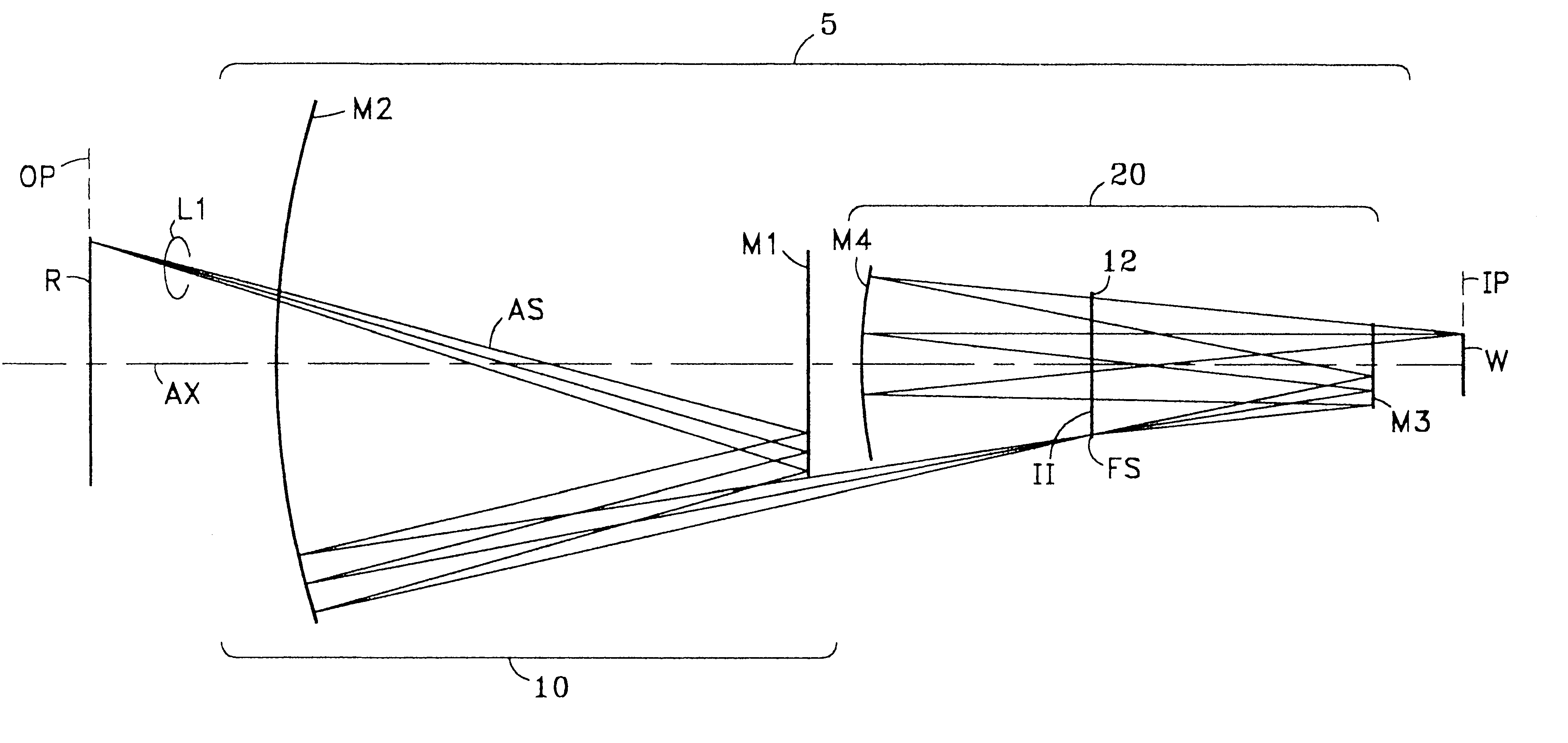
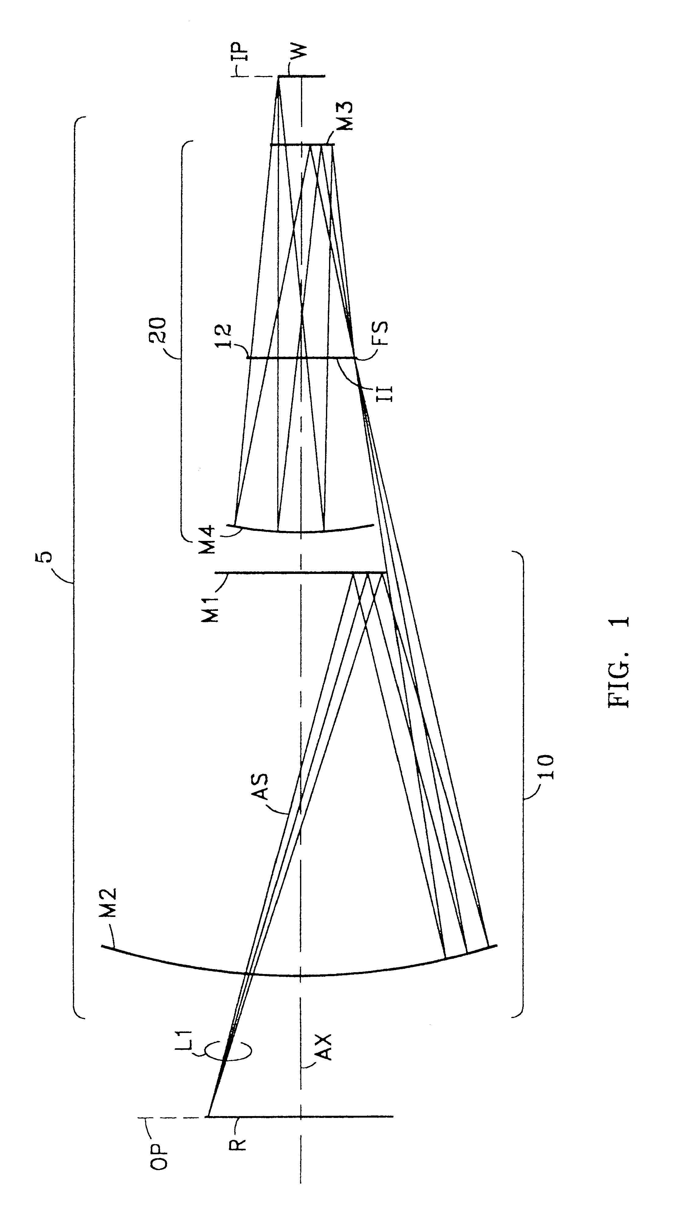
The following sets forth two numerical Working Examples of the catoptric reduction projection optical system according to the first aspect of the present invention. FIG. 1 is a cross-sectional optical diagram of the catoptric reduction projection optical system 5 of Working Example 1, as described above. FIG. 4 is a cross-sectional optical diagram of a catoptric reduction projection optical system 105 of Working Example 2. FIGS. 1 and 4 show only the lateral cross-sectional width of the light beams L1.

Catoptric reduction projection optical systems 5 and 105 of Working Example 1 and Working Example 2, respectively, have the general arrangement as described above with regard to system 5 of FIG. 1. Furthermore, in Working Example 1 shown in FIG. 1, mirror M1 has a rotationally symmetric aspherical surface shape having no paraxial power. In Working Example 2 shown in FIG. 4, mirror M1 has a rotationally symmetric aspherical surface having a concave shape. In addition, mirror M2 has a ro...

working example 1

In Working Example 1 and Working Example 2 discussed above, first catoptric optical system 10 and second catoptric optical system 20 have a reduction magnification. However, for example, first catoptric optical system 10 may have a reduction magnification and second catoptric optical system 20 may have a unity magnification or enlargement magnification, or the first catoptric optical system may have a unity magnification or enlargement magnification and the second catoptric optical system may have a reduction magnification.

Each of Working Examples 1 and 2 discussed above are constituted so that aperture stop AS is arranged in the optical path between first (object) plane OP and mirror M1. However, the arrangement of aperture stop AS having a shape that covers the entire circumference of light beam L1 (e.g., an aperture stop having a circular opening) may become difficult if the spacing in the direction orthogonal to optical axis AX between the optical path proceeding from first (obj...

working example 3

in FIG. 7 shows a catoptric reticle R. However, it is understood that the catoptric reduction imaging optical system according to either aspect of the present invention can also use a transparent reticle.

The present invention as described above teaches a catoptric reduction projection optical system that achieves sufficient imaging performance with a simple constitution. The system is ideally suited to, for example, X-ray lithography. By applying the system of the present invention to an exposure apparatus, a satisfactory reticle pattern image can be transferred onto a photosensitive substrate. In addition, by using the system of the present invention in a photolithography process that transfers a reticle pattern image onto a photosensitive substrate, a satisfactory reticle pattern image can be transferred onto the photosensitive substrate. This allows for satisfactory semiconductor devices to be manufactured.

Also, as described above, by using an aberration correction principle diff...


PUM

PropertyMeasurementUnit
angleaaaaaaaaaa
wavelengthaaaaaaaaaa
widthaaaaaaaaaa

Abstract

A catoptric reduction projection optical system (5) is provided with a first catoptric optical system (10) that images an object (R) in first (object) plane (OP) into a second plane (12) and forming an intermediate image (II) therein, and a second catoptric optical system (20) that images the intermediate image in the second plane onto a third (image) plane (IP), thereby forming a reduced image of the object in the first (object) plane onto the third (image) plane. The first catoptric optical system comprises a first mirror pair comprising two reflective mirrors (M1, M2). The second catoptric optical system comprises a second mirror pair comprising a convex mirror (M3) and a concave mirror (M4). The system also preferably satisfied a number of design conditions.

Description

FIELD OF THE INVENTIONThe present invention relates to photolithography, and in particular to catoptric reduction projection optical systems, and exposure apparatus and exposure methods for fabricating semiconductor and like devices using same.BACKGROUND OF THE INVENTIONWith the advance of micro-miniaturization in recent years in the manufacture of semiconductor and like devices, and semiconductor chip mounting boards, there has been a demand for higher resolving power in the exposure apparatus that prints the patterns therefor. To satisfy this demand, the wavelength of the light source of the exposure apparatus must be shortened and the NA (i.e., numerical aperture of the projection optical system) must be increased. Nevertheless, if the wavelength is shortened, optical glass that can withstand practical use is limited due to the absorption of light. Furthermore, when it comes to the short wavelengths of ultraviolet rays and X-rays, usable optical glass materials are nonexistent. I...

Claims


Application Information

Patent Timeline
Patent Type & Authority Patents(United States)
IPC IPC(8): G02B17/06G02B17/00G03F7/20
CPCG02B17/0657G03F7/70058G03F7/70233G03F7/7025G03F7/70275
Inventor TAKAHASHI, TOMOWAKISUENAGA, YUTAKA
Owner NIKON CORP
Why Eureka
Try Eureka