Catadioptric reduction projection optical system and exposure apparatus having the same

a technology of reduction projection and optical system, applied in the field of catadioptric reduction projection optical system and exposure apparatus, can solve the problems of insufficient abbe constant of synthetic quartz and fluorite, and shortwavelength, etc., to achieve excellent imaging performance and easy adjustment of optical system

Inactive Publication Date: 2004-02-24
NIKON CORP
View PDF73 Cites 95 Cited by
  • Summary
  • Abstract
  • Description
  • Claims
  • Application Information

AI Technical Summary

Benefits of technology

The present invention has as its object to provide a catadioptric reduction projection optical system which can use a beam splitting optical system smaller in size than a conventional polarizing beam splitter, can set a long optical path from a concave reflecting mirror to the image plane, can easily adjust the optical system, and has excellent imaging performance.

Problems solved by technology

If, however, the exposure wavelength is shortened, the types of optical glass which can be used in practice are limited because of the absorption of illumination light.
The difference between the Abbe constants of the synthetic quartz and the fluorite is not large enough to correct chromatic aberration.
For this reason, if the exposure wavelength becomes 300 nm or less, and a projection optical system is constituted by only a refracting optical system, chromatic aberration correction is very difficult to perform.
In addition, since fluorite undergoes a considerable change in refractive index with a change in temperature, i.e., has poor temperature characteristics, and involves many problems in a lens polishing process, fluorite cannot be used for many portions.
It is, therefore, very difficult to form a projection optical system having a required solution by using only a refracting system.
In this case, however, the projection optical system increases in size and requires aspherical reflecting surfaces.
It is very difficult to manufacture large, high-precision, aspherical surfaces

Method used


Image

  • Catadioptric reduction projection optical system and exposure apparatus having the same
  • Catadioptric reduction projection optical system and exposure apparatus having the same
  • Catadioptric reduction projection optical system and exposure apparatus having the same

Examples


first embodiment

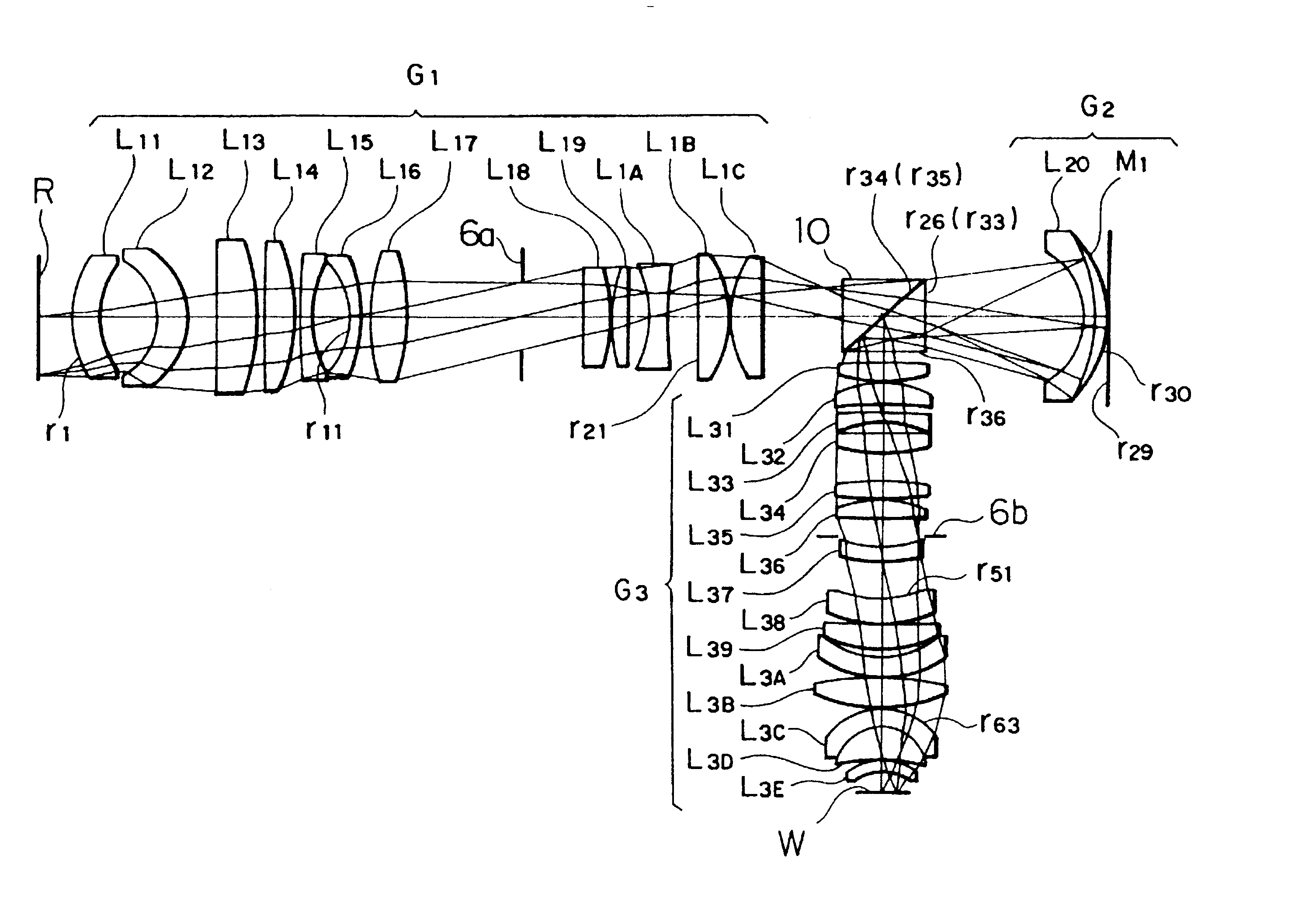
The first embodiment is a projection optical system suitable for a projection optical apparatus (e.g., a stepper) of a one-shot exposure method and having a magnification of 1 / 4.times..

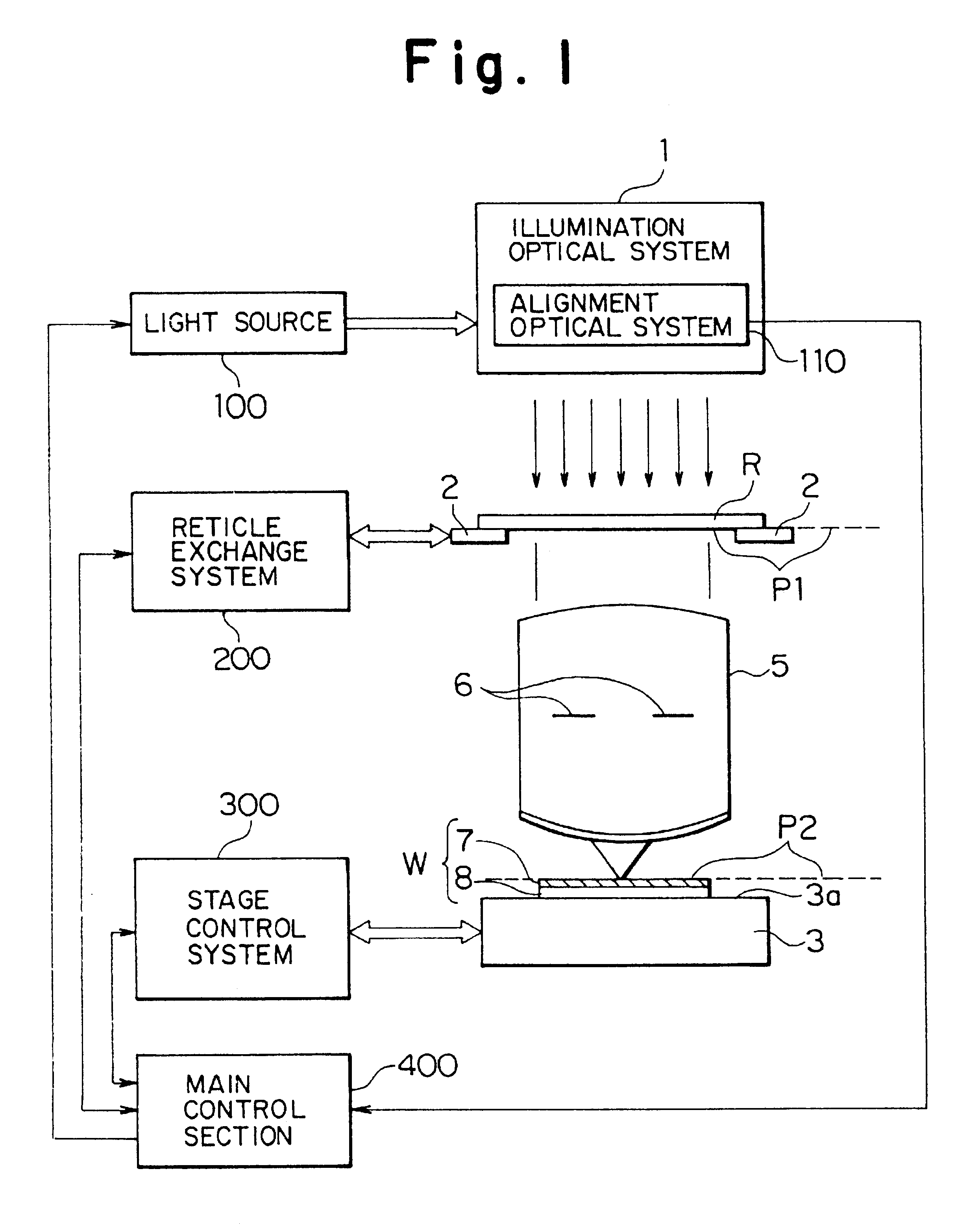
FIGS. 3 and 4 show the overall arrangement of the first embodiment. Referring to FIGS. 3 and 4, a reticle R (see FIG. 11) on which a pattern to be transferred is drawn is placed on an object plane P1, and a wafer W (see FIG. 11) coated with a photoresist is placed on an image plane P2. The reticle R on the object plane P1 is illuminated with exposure illumination light from the light source 100 of the illumination optical system 1, and a light beam passing through the reticle R forms a first intermediate image 9 via a refracting lens group G.sub.1 as a focusing lens group having a focal length f.sub.1. A light beam from the first intermediate image 9 is incident on a polarizing beam splitter (PBS) 10. A p-polarized light beam transmitted through a polarizing / reflecting surface 10a of the polarizing be...

second embodiment

The second embodiment is a projection optical system suitable for a projection optical apparatus based on the scanning exposure scheme and having a magnification of 1 / 4.times..

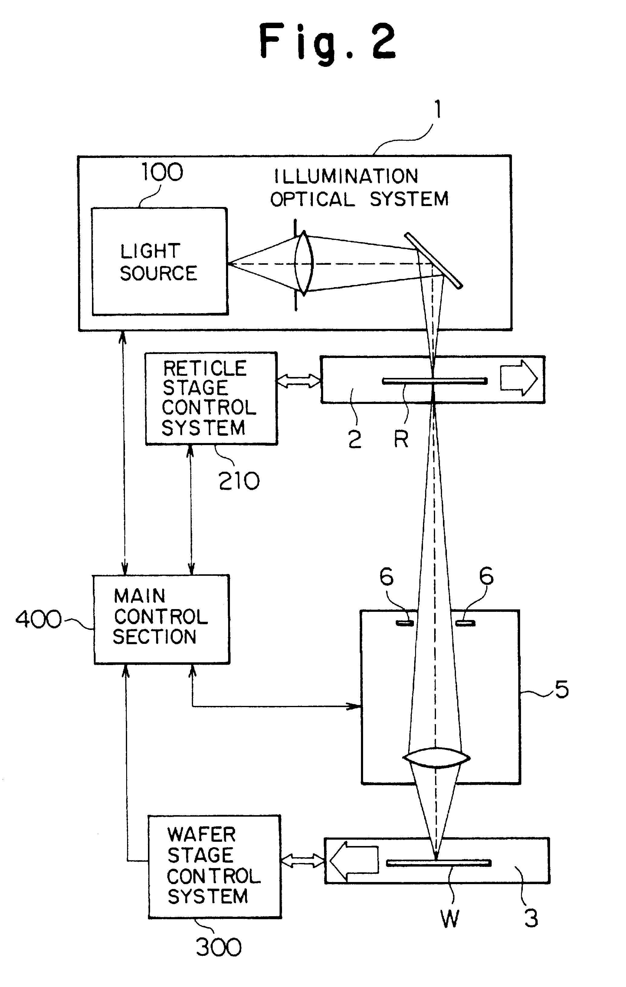
FIG. 5 shows the overall arrangement of the second embodiment. Referring to FIG. 5, a reticle R is placed on an object plane P1, and a wafer W is placed on an image plane P2. FIG. 6 is a plane view showing the reticle R when viewed in the direction of a refracting lens group G.sub.1 (f.sub.1) in FIG. 5. In this case, a bar-shaped illumination region 22, on the reticle R, which is slightly offset from the optical axis of the projection optical system is illuminated with illumination light from the light source 100 of the illumination optical system 1.

Referring to FIG. 5, a light beam passing through the illumination region 22 forms a first intermediate image 9 via the refracting lens group G.sub.1, and a light beam from the first intermediate image 9 passes through a side surface of a mirror (to be referred to ...

third embodiment

The third embodiment is a projection optical system suitable for a projection exposure apparatus of a scanning exposure method and having a magnification of 1 / 4.times.. A partial mirror is used in the third embodiment like in the second embodiment. However, an off-axis light ray further offset from the optical axis than in the second embodiment is used in the third embodiment.

FIG. 8 shows the overall arrangement of the second embodiment. Referring to FIG. 8 which indicates similar or same parts with the same reference numerals as in FIG. 5, a reticle 21 is placed on an object plane P1, and a wafer W is placed on an image plane P2. FIG. 9 is a plane view showing the reticle R when viewed in the direction of a refracting lens group G.sub.1 (f.sub.1). As shown in FIG. 9, an arcuated illumination region 22A, on the reticle R, which is slightly offset from the optical axis of the projection optical system is illuminated.

Referring to FIG. 8, a light beam passing through the illumination r...


PUM

PropertyMeasurementUnit
maximum field angleaaaaaaaaaa
field angleaaaaaaaaaa
heightaaaaaaaaaa

Abstract

A catadioptric projection optical system is provided, which can use a beam splitting optical system smaller in size than a conventional polarizing beam splitter, can set a long optical path from a concave reflecting mirror to an image plane, allows easy adjustment of the optical system, and has excellent imaging performance. A light beam from an object surface forms a first intermediate image through a refracting lens group. A light beam from the first intermediate image passes through a polarizing beam splitter and is reflected by a concave reflecting mirror to form a second intermediate image in the polarizing beam splitter. A light beam from the second intermediate image is reflected by the polarizing beam splitter means to form a final image on the image plane via a refracting lens group. The polarizing beam splitter means is arranged near the positions at which the intermediate images are formed.

Description

BACKGROUND OF THE INVENTION1. Field of the InventionThe present invention relates to a catadioptric reduction optical system suitably applied to a projection optical system for reduction projection in a projection exposure apparatus of a one-shot exposure method or a scanning exposure method, used to manufacture a semiconductor element or a liquid crystal display element in a photolithographic process and, more particularly, to a catadioptric reduction projection optical system having a magnification of about 1 / 4 to 1 / 5 with a resolution on the submicron order in the ultraviolet wavelength range.2. Related Background ArtIn fabricating semiconductor devices or liquid crystal display devices, etc. by photolithography process, the projection exposure apparatus is used for demagnifying through a projection optical system a pattern image on a reticle (or photomask, etc.) for example at a ratio of about 1 / 4 to 1 / 5 to effect exposure of the image on a wafer (or glass plate, etc.) coated wi...

Claims


Application Information

Patent Timeline
Patent Type & Authority Patents(United States)
IPC IPC(8): G02B17/08G03F7/20
CPCG02B17/08G02B17/0892G03F7/70225G03F7/70275G03F7/70358
Inventor TAKAHASHI, TOMOWAKI
Owner NIKON CORP
Why Eureka
Try Eureka