Hydrodynamic retarder

A technology of hydraulic reducer and container, applied in the field of hydraulic reducer, can solve the problems of manufacturing cost and cost of the reducer

Active Publication Date: 2014-10-01
VOITH PATENT GMBH
View PDF5 Cites 14 Cited by
  • Summary
  • Abstract
  • Description
  • Claims
  • Application Information

AI Technical Summary

Problems solved by technology

The disadvantage here is the considerable production and thus cost out

Method used


Image

  • Hydrodynamic retarder
  • Hydrodynamic retarder
  • Hydrodynamic retarder

Examples


Embodiment Construction

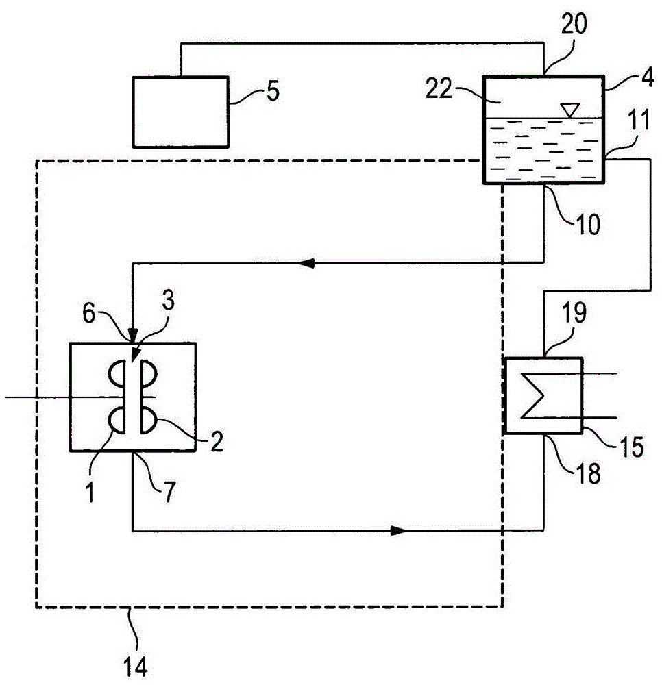
[0030] figure 1 A schematic diagram of a hydrodynamic retarder arranged in an external cooling circuit is shown. The latter consists of a bladed and rotating primary wheel, designated rotor 1 , and a stationary, non-rotating, also bladed secondary wheel, designated stator 2 . The rotor 1 and the stator 2 jointly form an annular working chamber 3 . Furthermore, a working medium container 4 is provided for storing working medium that is temporarily not in the working chamber 3 . Oil, water or a water mixture can be used as the working medium. The external cooling circuit shown can at the same time be the cooling circuit of a vehicle such as a truck or a rail vehicle, so that the cooling medium of the cooling circuit is at the same time the working medium of the hydrodynamic retarder.

[0031] The working medium container 4 includes an outlet 10 , which is connected to the first working medium connection 6 via a drain connection for conveying the working medium from the workin...


PUM


Abstract

The invention relates to a hydrodynamic retarder comprising - a rotor (1) and a stator (2) which form a working chamber (3) with each other; - a first working medium connection (6); - a second working medium connection (7); and - a working medium container (4) that has an outlet (10), which is connected to the first working medium connection via a line, and an inlet (11), which is connected to the second working medium connection via a line; wherein - the working medium container is made of two housing parts (8, 9), which are joined together along a parting line (12). According to the invention: - the two housing parts together enclose the working medium storage volume; - one of the two housing parts simultaneously forms a part of a retarder housing (14) which supports or forms the stator and partly forms all or some of the working medium-conducting connections between the working medium storage volume and the working chamber; and - a separating plate (13) is inserted between the two housing parts, said separating plate together with one or both of the housing parts forming cavities for the working medium-conducting connections and/or the working medium storage volume.

Description

technical field [0001] The invention relates to a hydrodynamic retarder according to the preamble of claim 1 in details. Furthermore, the invention relates to a method for producing such a gear unit. Background technique [0002] The hydrodynamic retarder has a working chamber which can be filled with a working medium and which can be emptied in order to transmit the torque of the vaned primary wheel, also called the rotor, to the secondary wheel, also called the stator. When the working chamber has been filled, the primary wheel is decelerated and thus a particular shaft that is non-rotatably fixed to the primary wheel, such as a steering shaft or a drive output shaft that is directly connected to the wheels of the vehicle, is decelerated. [0003] Conventionally, hydrodynamic retarders are cooled by an external oil- or water cooling circuit in order to dissipate the heat generated during operating braking. In this case, the working medium does not remain permanently insi...

Claims


Application Information

Patent Timeline
IPC IPC(8): B60T1/087F16D57/02
CPCF16D57/04F16D57/02B60T1/087B60T10/02B22D18/00F16D65/78
Inventor 迪特尔·劳克曼
Owner VOITH PATENT GMBH
Why Eureka
Try Eureka