Hydraulic automatic tensioner

一种张紧器、自动的技术,应用在传动装置、皮带/链条/齿轮、机械设备等方向,能够解决制造成本高、加工困难、液压阻尼不良等问题,达到可靠性提高的效果

Active Publication Date: 2014-10-01
NTN CORP
View PDF10 Cites 4 Cited by
  • Summary
  • Abstract
  • Description
  • Claims
  • Application Information

AI Technical Summary

Problems solved by technology

[0008] In the hydraulic automatic tensioner described in Patent Document 1, when the relief valve is opened, the working oil in the pressure chamber is instantly withdrawn from the communication path to the liquid storage chamber, so that a sudden pressure drop occurs in the pressure chamber, and due to This pressure drop causes the air dissolved in the working oil to precipitate and accumulate in the pressure chamber. When the hydraulic automatic tensioner is pressed, the residual air will be compressed to cause poor hydraulic damping, leaving room for improvement.
[0009] In addition, in the above-mentioned hydraulic automatic tensioner, the relief valve is configured such that the valve seat is pressed into the valve fitting hole, and the valve body for opening and closing formed in the valve hole of the valve seat is pressed in the closing direction by the valve spring. Force, a spring seat is installed between the valve spring and the valve body, and the protruding shaft part protruding from the upper surface of the spring seat abuts against the upper wall surface of the valve fitting hole to limit the opening amount of the valve body. Since the upper surface of the protruding shaft collides with the above-mentioned upper wall surface, there is a possibility that the upper surface may be worn or deformed to block the end opening of the communication path, so there is room for improvement in improving the reliability of the relief valve.
[0010] In addition, since the protruding shaft has a small diameter, it is difficult to process and the manufacturing cost is high, so there is room for improvement in reducing the cost.

Method used


Image

  • Hydraulic automatic tensioner
  • Hydraulic automatic tensioner
  • Hydraulic automatic tensioner

Examples


Embodiment Construction

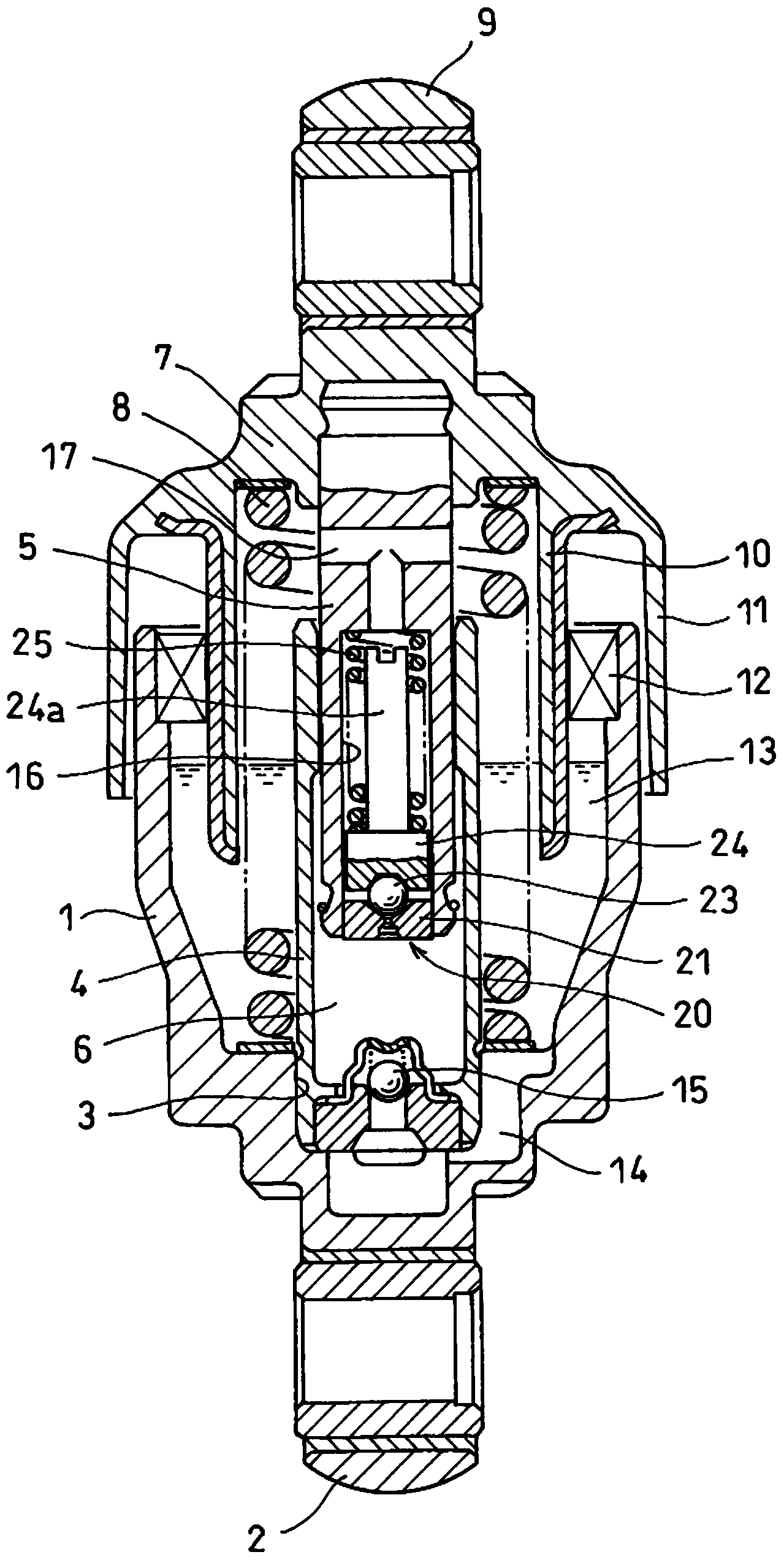
[0048] Embodiments of the present invention will be described below with reference to the drawings. Such as figure 1 As shown, the lower part of the cylinder block 1 is closed, and a connecting piece 2 rotatably connected to the engine block is provided at the closed end thereof.

[0049] A sleeve fitting hole 3 is provided on the bottom surface of the cylinder body 1 , and the lower end portion of the sleeve 4 is press-fitted into the sleeve fitting hole 3 . The lower portion of the rod 5 is slidably inserted into the sleeve 4 , and a pressure chamber 6 is provided in the sleeve 4 by the insertion of the rod 5 .

[0050] Be positioned at the outer upper end of cylinder body 1 at rod 5, be fixed with spring seat 7, the back-moving spring 8 that packs between this spring seat 7 and the bottom surface of cylinder body 1 is opposite cylinder body 1 and rod 5 to the direction of relative elongation. Apply force.

[0051] On the upper end of the spring seat 7, there is a Figur...


PUM


Abstract

Provided is a hydraulic automatic tensioner capable of preventing the occurrence of hydraulic damper defects and also capable of preventing hydraulic damper delay. The lower end part of a sleeve (4) is press-fitted into a sleeve fitting hole (3) formed in the bottom surface of a cylinder (1), the lower end part of a rod (5) slidably fits inside the sleeve (4), and a return spring (8) is mounted between a spring seat (7) provided to the upper part of the rod (5) and the bottom surface of the cylinder (1). A channel (14) for providing communication between a pressure chamber (6) and a reservoir chamber (13) is formed between the sleeve fitting hole (3) and the fitting surface of the sleeve (4), and a check valve (15) is mounted in the channel (14). A valve fitting hole (16) and a communication channel (17) for providing communication between and the valve fitting hole (16) and the reservoir chamber (13) are formed in the rod (5), and a relief valve (20) is mounted inside the valve fitting hole (16). An orifice (27) is formed between a valve element (23) and a valve hole (22) formed in the valve seat (21) of the relief valve (20), and a sudden pressure reduction in the pressure chamber (6) is inhibited by the orifice (27).

Description

technical field [0001] The present invention relates to a hydraulic automatic tensioner used for tension adjustment of belts driving alternators, water pumps, compressors of air conditioners and other automobile auxiliary machines. Background technique [0002] In belt transmissions that transmit the rotation of the crankshaft of the engine to various automotive accessories, such as Figure 13 As shown, on the slack side of the belt 51, a pulley arm 53 that can swing around the fulcrum shaft 52 is provided, and the adjustment force of the hydraulic automatic tensioner A is applied to the pulley arm 53, and is supported by the above pulley. A rotatable tension pulley 54 at the swing side end of the arm 53 biases the pulley arm 53 in a direction in which the belt 51 is pressed, and keeps the tension of the belt 51 constant. [0003] As the conventional hydraulic automatic tensioner A used in the above-mentioned belt transmission device, there is known a device in which a rod i...

Claims


Application Information

Patent Timeline
Patent Type & Authority Applications(China)
IPC IPC(8): F16H7/12
CPCF16H2007/0814F16H2007/0806F16H7/08F16H2007/0859F16H7/1236F16H2007/0893
Inventor 田中唯久北野聪高野武博
Owner NTN CORP
Why Eureka
Try Eureka