MR imaging with B1 mapping

An imaging sequence, body technology, applied in the field of computer programs, can solve problems such as limiting dynamic range, achieve the effects of robust motion resistance, avoiding layer crosstalk, and easy signal evaluation

Active Publication Date: 2014-10-01
KONINKLJIJKE PHILIPS NV
View PDF6 Cites 9 Cited by
  • Summary
  • Abstract
  • Description
  • Claims
  • Application Information

AI Technical Summary

Problems solved by technology

This disadvantageously limits the known B 1 Dynamic scope of mapping methods

Method used


Image

  • MR imaging with B1 mapping
  • MR imaging with B1 mapping
  • MR imaging with B1 mapping

Examples


Embodiment Construction

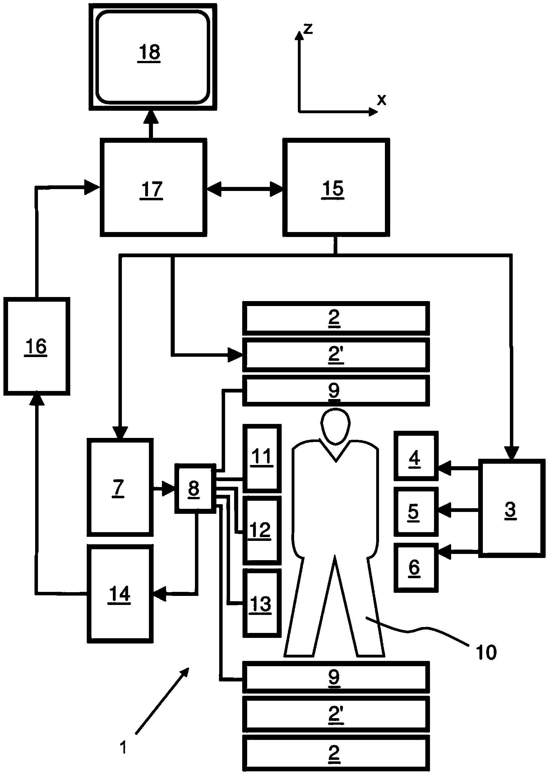
[0062] refer to figure 1 , shows the MR device 1 . The device comprises superconducting or normally conducting main magnet coils 2, thereby creating a substantially uniform, temporally constant main magnetic field B along the z-axis through the examination volume 0 . The device also comprises a set (first order, second order, and where applicable third order) of shim coils 2', wherein the current flowing through the individual shim coils of the set 2' the B 0 The purpose of deviation minimization is controllable.

[0063] Magnetic resonance generation and manipulation systems apply a series of RF pulses and switched magnetic field gradients to invert or excite nuclear magnetic spins, induce magnetic resonance, refocus magnetic resonance, manipulate magnetic resonance, spatially or otherwise encode said magnetic resonance , saturating spins, etc., to perform MR imaging.

[0064] More specifically, the gradient pulse amplifier applies current pulses to selected ones of the ...


PUM


Abstract

The invention relates to a method of MR imaging. A portion of a body placed in the examination volume of an MR device is subjected to an imaging sequence of RF pulses and switched magnetic field gradients. The imaging sequence is a stimulated echo sequence including i) two preparation RF pulses (alpha) radiated toward the portion of the body during a preparation period (21), and ii) reading RF pulses (beta) radiated toward the portion of the body during an acquisition period (22) temporally subsequent to the preparation period (21). FID signals (I1) and one or more stimulated echo signals I2) are acquired during the acquisition period (22) with equal T2*-weighting. A B1 map indicating the spatial distribution of the RF field of the preparation RF pulses within the portion of the body is derived from the acquired FID (I1) and stimulated echo (I2) signals.

Description

technical field [0001] The present invention relates to the field of magnetic resonance (MR) imaging. It concerns methods of MR imaging of at least parts of the body. The invention also relates to an MR device and a computer program to be run on the MR device. Background technique [0002] Image-forming MR methods that exploit the interaction between magnetic fields and nuclear spins to form two- or three-dimensional images are widely used today, especially in the field of medical diagnosis, because they are superior in many ways to imaging soft tissues Other imaging methods, do not require ionizing radiation and are usually noninvasive. [0003] According to the general MR method, the body of the patient to be examined is placed in a strong, uniform magnetic field (B 0 field), the direction of the magnetic field simultaneously defines the axis (typically the z-axis) of the coordinate system on which the measurement is based. Depends on an electromagnetic alternating fie...

Claims


Application Information

Patent Timeline
Patent Type & Authority Applications(China)
IPC IPC(8): G01R33/24
CPCG01R33/246G01R33/243G01R33/50G01R33/54G01R33/24
Inventor K·内尔克P·博尔纳特I·格雷斯林U·卡切尔C·洛斯勒H·埃格斯
Owner KONINKLJIJKE PHILIPS NV
Why Eureka
Try Eureka