
Device for reshaping product

A product and component technology, which is applied in the field of product shaping devices, can solve problems such as irregular shape deformation, limited shaping fixtures, and inability to freely control changes in bending and rebound of finished products, and achieve adjustable speed, aging and high cost effect

Active Publication Date: 2014-10-08
昆山能缇精密电子有限公司
View PDF5 Cites 0 Cited by
  • Summary
  • Abstract
  • Description
  • Claims
  • Application Information

AI Technical Summary

Problems solved by technology

[0002] Products manufactured in a natural stamping environment will be deformed, but the product stack will also squeeze the surface of each other, resulting in irregular deformation, especially sheet metal stamping parts, the traditional artificial shaping method, due to the different magnitude of artificial force , so that the product will have different deformation trends and trends when viewed from the surface and material thickness, and in the process of plastic surgery, the product will inevitably scratch the human hand
[0003] Another common method is to use the traditional horizontal leveling machine or plastic jig, but the traditional horizontal leveling machine can only be aimed at the leveling of the product, and cannot freely control the bending and rebound changes of the finished product, and there is no visualization. Once you encounter the need to specify the bending angle of the product, you can only give up using it. For the product shaping jig, although the same product can be used for shaping and using the same bending degree, the same product can be used in the stamping process. Among them, due to the difference of punch force and raw materials, there will be relatively different degrees of bending deformation, which limits the use of plastic fixtures, and cannot produce good finished products, so they can only be discarded or remade. fixture

Method used


Image

  • Device for reshaping product
  • Device for reshaping product
  • Device for reshaping product

Examples


Embodiment Construction

[0017] The present invention will be further described below in conjunction with specific examples. It should be understood that these examples are only used to illustrate the present invention and are not intended to limit the scope of the present invention. In addition, it should be understood that after reading the teachings of the present invention, those skilled in the art can make various changes or modifications to the present invention, and these equivalent forms also fall within the scope defined by the appended claims of the application.

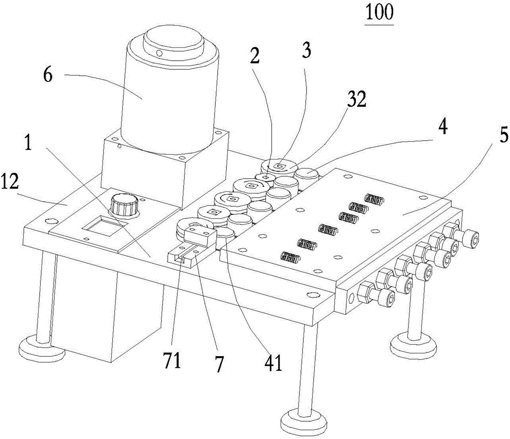
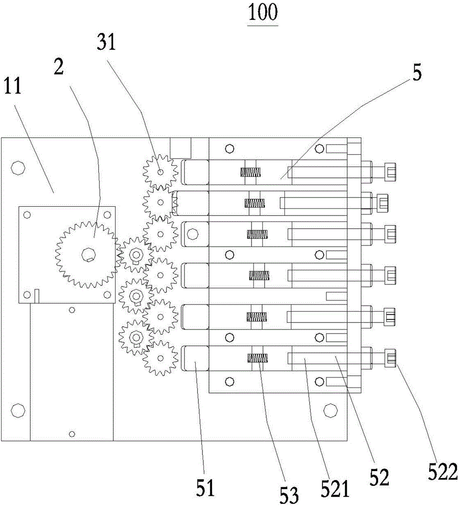
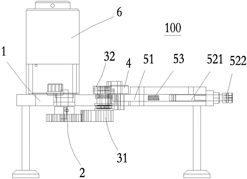
[0018] Please refer to Figure 1 to Figure 3 Shown is a schematic structural view of the device 100 for shaping products according to the present invention, which includes a main body 1, a transmission mechanism 2, several driving wheel assemblies 3, several follower wheel assemblies 4, an external force speed regulating motor 6 and an adjusting mechanism 5.

[0019] The main body 1 has a platform 12 with a plate-shaped structure, ...


PUM


Abstract

The invention discloses a device for reshaping a product. The device comprises a body, a transmission mechanism, a plurality of driving wheel assemblies, a plurality of follower wheel assemblies and an outer force speed regulating motor, wherein the transmission mechanism, the driving wheel assemblies, the follower wheel assemblies and the outer force speed regulating motor are installed on the body, the transmission mechanism is connected with the outer force speed regulating motor and the driving wheel assemblies. The device is characterized by further comprising a adjusting mechanism in contact with the follower wheel assemblies and used for driving the follower wheel assemblies to perform displacement, and gaps are reserved between the follower wheel assemblies and the driving wheel assemblies. The device for reshaping the product can rapidly enable the product reshaping to be stable, enable regulation and control to be visible, enable the product to be flattened and enable two ends of the product to upward in a reshaping range, the whole process is safe and controllable, the speed is adjustable, and the device has very high value on aging and cost.

Description

【Technical field】 [0001] The invention relates to the technical field of product shaping machinery, in particular to a device for shaping products. 【Background technique】 [0002] Products manufactured in a natural stamping environment will be deformed, but the product stack will also squeeze the surface of each other, resulting in irregular deformation, especially sheet metal stamping parts, the traditional artificial shaping method, due to the different magnitude of artificial force , so that the product will have different deformation trends and directions when viewed from the surface and material thickness, and in the process of plastic surgery, the product will inevitably scratch the human hand. [0003] Another common method is to use the traditional horizontal leveling machine or plastic jig, but the traditional horizontal leveling machine can only be aimed at the leveling of the product, and cannot freely control the bending and rebound changes of the finished produc...

Claims


Application Information

Patent Timeline
Patent Type & Authority Applications(China)
IPC IPC(8): B21D1/02
Inventor 曾耿谆
Owner 昆山能缇精密电子有限公司
Learn More