
Cable Y-shaped joint shaping device

A shaping device and cable technology, applied in the field of local shaping of workpieces and machining, can solve the problems of inconvenient cable clamping and positioning, inability to squeeze and shape pin wiring and so on.

Pending Publication Date: 2020-04-28
SUZHOU INST OF INDAL TECH
View PDF1 Cites 0 Cited by
  • Summary
  • Abstract
  • Description
  • Claims
  • Application Information

AI Technical Summary

Problems solved by technology

However, the shaping structure of the pin terminal of the workpiece cannot be partially shaped, nor can the pin wiring of the workpiece be partially squeezed and shaped, and it is not easy to clamp and position the cable.

Method used


Image

  • Cable Y-shaped joint shaping device
  • Cable Y-shaped joint shaping device
  • Cable Y-shaped joint shaping device

Examples


Embodiment Construction

[0021] The present invention will now be further described in detail with reference to the accompanying drawings and embodiments. These drawings are all simplified schematic diagrams, and only illustrate the basic structure of the present invention in a schematic manner, so they only show the structures related to the present invention.

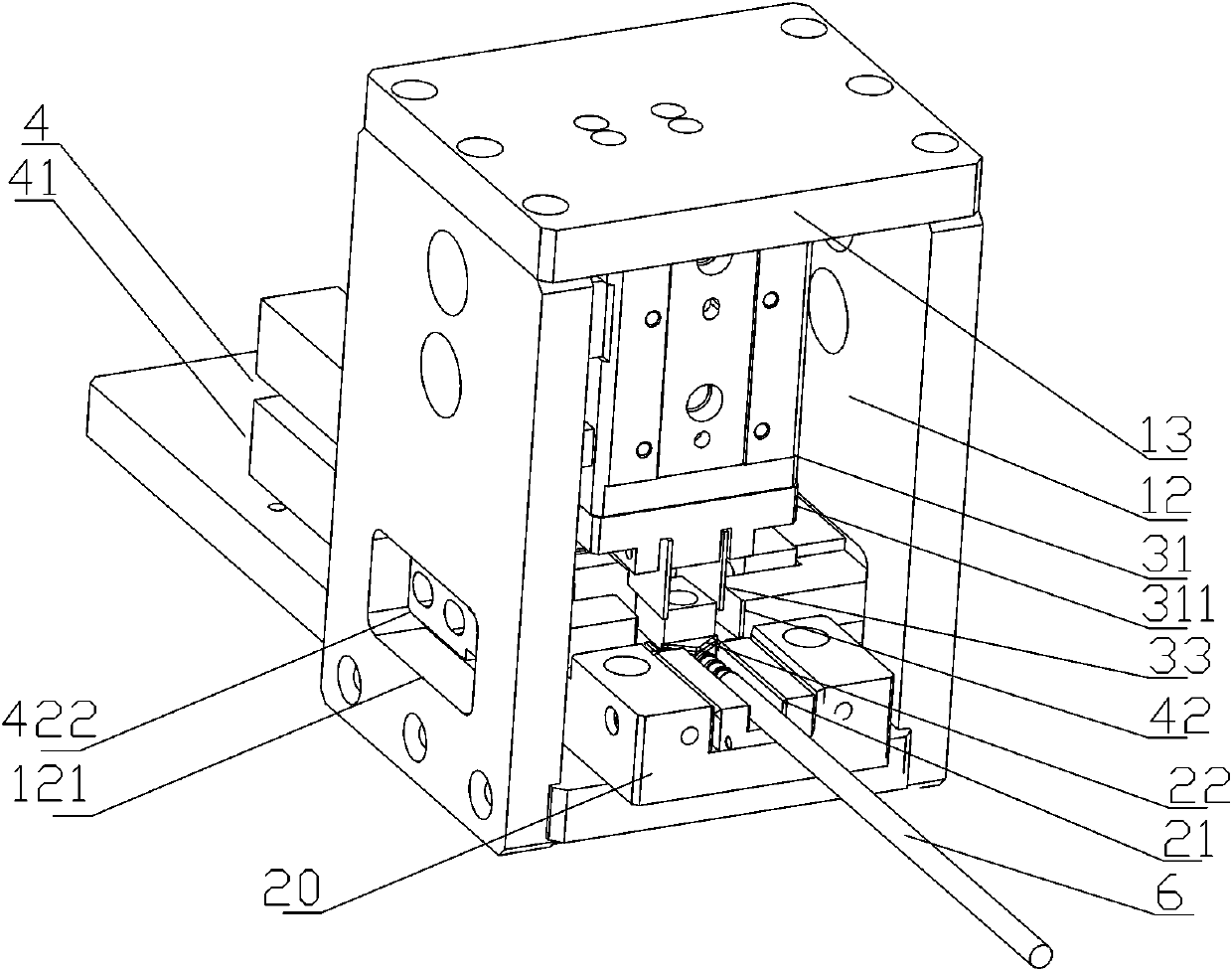
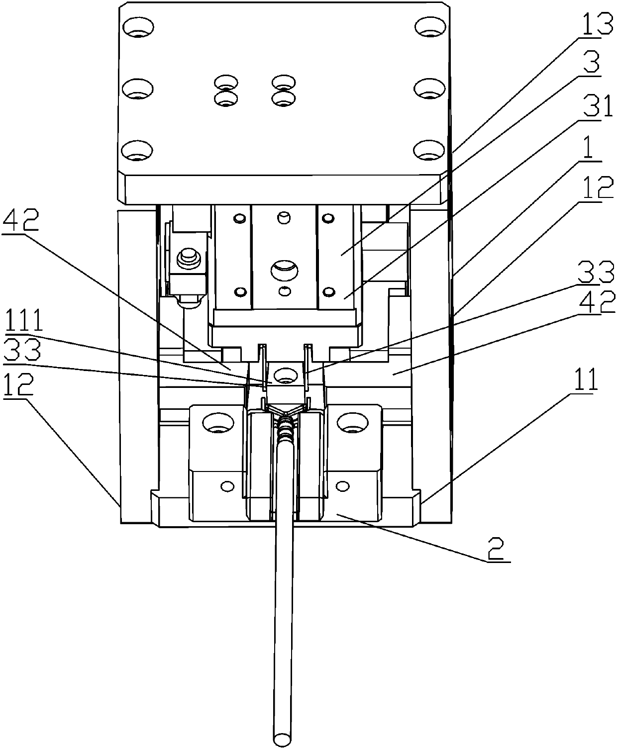
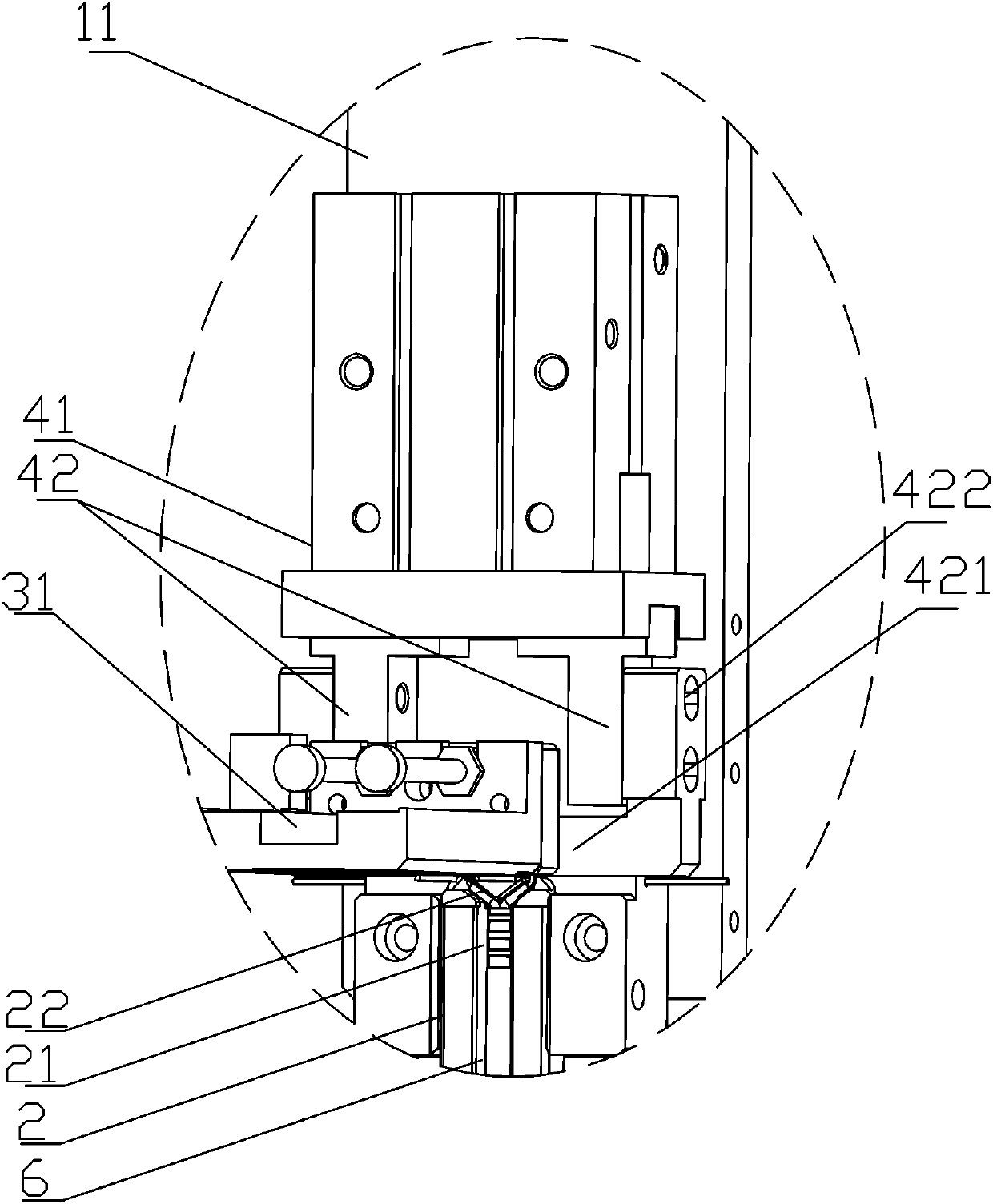
[0022] like Figure 1~Figure 4 As shown, the present embodiment discloses a cable Y-shaped joint shaping device, including a positioning die 2 for positioning the workpiece 6, the positioning die 2 includes a workpiece die 20 provided with a workpiece groove 21, and one end of the workpiece groove 21 is provided with a The inverted triangular positioning block 22 is formed between the positioning block 22 and the workpiece slot 21 to form a Y-shaped accommodating slot for accommodating the workpiece, that is, the cable lead; the other end of the workpiece slot 21 is provided with a limit holder 23 for holding the workpiece.

[0023] The limit...


PUM


Abstract

The invention relates to a cable Y-shaped joint shaping device. The cable Y-shaped joint shaping device comprises a positioning die used for positioning a workpiece, wherein a concentric-square-shapedsupporting frame is arranged at one end of the positioning die, a through cavity corresponding to the positioning die is formed in the supporting frame, and a workpiece shaping device is arranged inthe through cavity; the workpiece shaping device comprises an abutting block arranged in the through cavity, an upper shaping device arranged on the upper portion of the supporting frame and a side shaping device arranged at one end of the through cavity; and the side shaping device comprises at least one pair of side pushing blocks which are arranged on the two sides of the through cavity respectively and can be opened and closed relative to the abutting block. The cable Y-shaped joint shaping device can stably clamp, shape and position a cable and can quickly and effectively shape a pin of awiring end of the cable into a Y-shaped joint structure.

Description

technical field [0001] The invention relates to the field of machining, mainly to the field of local shaping of workpieces, and in particular to a shaping device for a Y-shaped joint of a cable. Background technique [0002] Existing patent: workpiece shaping device (patent number: CN201721274588.5), which discloses a workpiece shaping device, including: an upper die, including an elastic pressing block; a lower die, including a lower die fixing plate and two equal-height blocks , two equal-height blocks are arranged on one side of the lower mold fixing plate opposite and spaced along the first direction, one end of one equal-height block is provided with a first spacer block, and one end of the other equal-height block is provided with a second spacer block, The first cushion block and the second cushion block are staggered in the second direction; wherein, the first direction and the second direction are perpendicular to each other. In the above-mentioned workpiece shapin...

Claims


Application Information

Patent Timeline
Patent Type & Authority Applications(China)
IPC IPC(8): B21F1/02
CPCB21F1/02
Inventor 黄华栋孙宝玉许童王耀袁泉
Owner SUZHOU INST OF INDAL TECH
Learn More