A circulating cooling structure for grinding and polishing disc

A circulating cooling and polishing disc technology, applied in the field of grinding, grinding and polishing equipment, can solve the problems of difficulty in meeting workpiece processing requirements, low efficiency, and difficulty in realizing active cooling of the lower grinding and polishing disc, and achieve the effect of precise temperature control

Active Publication Date: 2016-04-13
YUHUAN CNC MACHINE TOOL
View PDF7 Cites 0 Cited by
  • Summary
  • Abstract
  • Description
  • Claims
  • Application Information

AI Technical Summary

Problems solved by technology

Due to the existence of the empty rotating shaft 2 and the separation of the rotating action, the cooling water cannot be sent to the grinding and polishing disc B through the empty rotating shaft 2, making it difficult to realize the active cooling of the lower grinding and polishing disc. For a long time, this type of grinding and polishing equipment The lower grinding and polishing discs adopt a passive cooling method, that is, the heat during work is indirectly transferred through the external grinding liquid and air, which makes it difficult to control the working temperature of the grinding and polishing disc. The uncontrollable grinding and polishing temperature makes it difficult to reach the workpiece when processing special parts. Processing requirements, scrap rate, high cost of parts processing, low efficiency

Method used


Image

  • A circulating cooling structure for grinding and polishing disc
  • A circulating cooling structure for grinding and polishing disc

Examples


Embodiment Construction

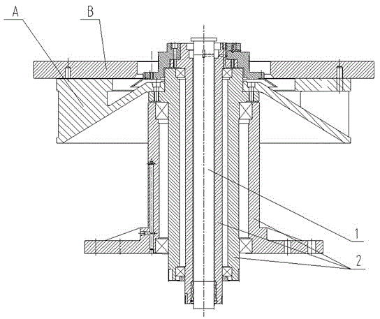
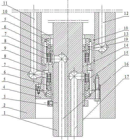
[0014] see figure 2 , a circulating cooling structure for grinding and polishing discs, including a central rotating shaft 1 and an empty sleeve rotating shaft 2 sleeved on the central rotating shaft 1 with a gap, and a sealing device is provided in the gap between the empty sleeve rotating shaft 2 and the central rotating shaft 1 , the sealing device is provided with a water inlet chamber 15 and a water outlet chamber 13 that are not connected to each other, and the central rotating shaft 1 is provided with a first water inlet 17 and a first water outlet 16 connected with a rotary joint (not shown) , the empty sleeve rotating shaft 2 is provided with a second water inlet 11 and a second water outlet 12 communicating with the grinding and polishing disc (not shown), and the first water inlet 17 and the first water outlet 16 pass through the inlet and outlet respectively. The water chamber 15 and the water outlet chamber 13 communicate with the second water inlet 11 and the se...


PUM


Abstract

The invention discloses a circulating cooling structure for a grinding and polishing disc. The circulating cooling structure comprises a central rotating shaft and a gap sleeve rotating shaft, wherein the central rotating shaft is sleeved with the gap sleeve rotating shaft in a gapped mode. A sealing device is arranged in the gap formed between the gap sleeve rotating shaft and the central rotating shaft. The sealing device is provided with a water inlet cavity and a water outlet cavity which is not communicated with the water inlet cavity. A first water inlet channel and a first water outlet channel which are connected with a rotating joint are arranged in the central rotating shaft. A second water inlet channel and a second water outlet channel which are communicated with the grinding and polishing disc are arranged on the gap sleeve rotating shaft. The first water inlet channel and the first water outlet channel are communicated with the second water inlet channel and the second water outlet channel through the water inlet cavity and the water outlet cavity respectively. According to the circulating cooling structure for the grinding and polishing disc, active circulating cooling of the disc face of the grinding and polishing disc can be achieved, a large amount of heat generated during polishing can be emitted out in time, accurate temperature control is achieved, grinding and polishing precision and efficiency can be improved, and the requirements for different material machining can be met.

Description

technical field [0001] The invention belongs to grinding and polishing equipment, in particular to a circulation cooling structure for a grinding and polishing disc. Background technique [0002] In the equipment currently used for grinding and polishing, the cooling methods of the grinding and polishing disc under it are divided into two types: active cooling and passive cooling. [0003] passive cooling in the form of figure 1 As shown, there are rotating parts such as the central rotating shaft 1, the tray A, and the grinding and polishing disc B in the lower transmission part. In order to realize the rotation action requirements of the lower transmission part of the equipment, a multi-stage empty sleeve rotating shaft 2 is set. Through the motor Drive different rotating shafts to achieve different rotation requirements of different functional components. Due to the existence of the empty rotating shaft 2 and the separation of the rotating action, the cooling water cann...

Claims


Application Information

Patent Timeline
Patent Type & Authority Patents(China)
IPC IPC(8): B24B55/02B24B37/34
CPCB24B37/34B24B55/02
Inventor 许亮彭关清陈永福裴化君杜群波
Owner YUHUAN CNC MACHINE TOOL
Why Eureka
Try Eureka