
Engine cover locking mechanism

A technology of engine hood and locking mechanism, which is applied in the direction of upper structure, upper structure sub-assembly, transportation and packaging, etc. It can solve the problems of scratching fingers, high requirements for layout space and position, and achieve the effect of preventing abnormal opening

Inactive Publication Date: 2014-10-08
卢世清
View PDF5 Cites 1 Cited by
  • Summary
  • Abstract
  • Description
  • Claims
  • Application Information

AI Technical Summary

Problems solved by technology

In the prior art, the two locking mechanisms are arranged at the front end of the hood, which requires relatively high layout space and position, especially for the secondary lock mechanism, which needs to consider many technical issues such as opening space and opening force, and at the same time, due to the layout position of the secondary lock of each model Different from the opening form, it often takes multiple attempts to touch the opening handle during use, and there is a risk of scratching fingers, which causes a lot of inconvenience to users, so a hood secondary lock opening mechanism with simple structure and convenient operation is needed
[0003] The two locking mechanisms of the existing engine hood are arranged at the front end of the engine hood, which requires relatively high layout space and position, especially for the auxiliary lock mechanism, which needs to consider many technical issues such as opening space and opening force. The position and the opening form are different, and it often takes multiple attempts to touch the opening handle when using it, and there is a risk of scratching fingers, causing a lot of inconvenience to users

Method used


Image

  • Engine cover locking mechanism
  • Engine cover locking mechanism

Examples


Embodiment Construction

[0012] The principles and features of the present invention are described below in conjunction with the accompanying drawings, and the examples given are only used to explain the present invention, and are not intended to limit the scope of the present invention.

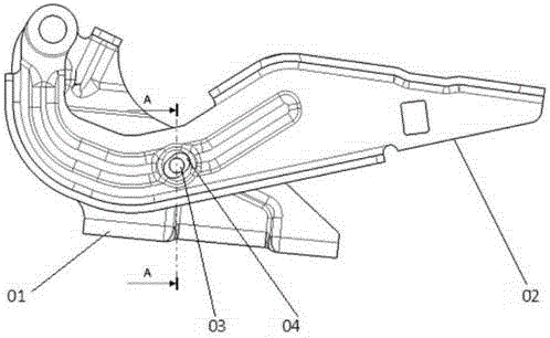
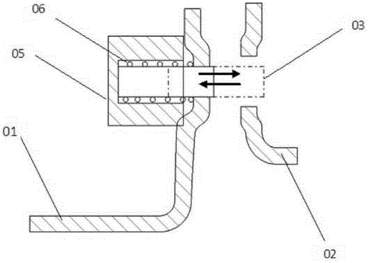
[0013] Such as figure 1 , figure 2 As shown, a hood locking mechanism includes a hood, a hinge, a hood lock and a hood position switch (the hood position switch is used to check whether the hood lock is locked in place), the hood lock and the hood The position switch is installed on the engine cover, and the hinge includes a fixed blade 01, a movable blade 02, a pin shaft 03 and an electromagnetic actuator 05; the fixed blade 01 is installed on the vehicle body, and the fixed blade 01 01 is provided with a fixed blade limit hole; the movable blade 02 is installed on the engine cover, and the movable blade 02 is provided with a movable blade limit hole 04; the movable blade 02 and the fixed The leaf plates 01 are ...


PUM


Abstract

The invention relates to an engine cover locking mechanism. The engine cover locking mechanism comprises an engine cover, a hinge, an engine cover lock and an engine cover position switch. The engine cover lock and the engine cover position switch are mounted on the engine cover; the hinge comprises a fixed leaf, a movable leaf, a hinge pin and an electromagnetic executing device, wherein the fixed leaf and the movable leaf are mounted on a vehicle body, the fixed leaf is provided with a fixed leaf limiting hole, the movable leaf is provided with a movable leaf limiting hole, the movable leaf and the fixed leaf are hinged to each other, and the electromagnetic executing device is fixedly connected with the fixed leaf and connected with the hinge pin. The engine cover locking mechanism has the advantages of not only meeting regulatory requirements, but also achieving automatic starting of engine cover locking, thereby bring great convenience to users, and meanwhile, due to the fact that the locking mechanism is arranged on the hinge, avoiding influence on protection of pedestrians in front of the engine cover.

Description

technical field [0001] The invention relates to the technical field of automobiles, in particular to an engine cover locking mechanism. Background technique [0002] According to regulations, in order to ensure driving safety, the engine hood requires two locking mechanisms to ensure that when the main lock fails during driving, the auxiliary lock can effectively ensure that the engine hood is in a closed position, preventing accidental opening, affecting the driver's vision and causing traffic ACCIDENT. In the prior art, the two locking mechanisms are arranged at the front end of the hood, which requires relatively high layout space and position, especially for the secondary lock mechanism, which needs to consider many technical issues such as opening space and opening force, and at the same time, due to the layout position of the secondary lock of each model Different from the opening form, it often takes multiple attempts to touch the opening handle during use, and there...

Claims


Application Information

Patent Timeline
IPC IPC(8): B62D25/12
Inventor 卢世清
Owner 卢世清
Learn More