Long-distance heavy-load drag chain supporting device

A long-distance drag chain technology, applied in the field of drag chains, can solve the problems of unsuitable closed drag chains and worn drag chains, and achieve the effects of improving service life, reducing quantity, and ensuring operation reliability

Active Publication Date: 2014-10-08
ZHEJIANG JINFULONG MACHINE TOOL ACCESSORIES
View PDF6 Cites 11 Cited by
  • Summary
  • Abstract
  • Description
  • Claims
  • Application Information

AI Technical Summary

Problems solved by technology

[0002] The long-distance heavy-duty towline can be divided into three parts during the movement, the lower section of the towline, the steering ring section of the towline and the upper section of the towline. The lower section of the towline is laid flat on the supporting frame of the towline. Due to the load, it is stacked on the top of the lower section of the towline, while the turning ring section of the towline forms a circular closed shape. Since the upper section of the towline is stacked on the lower section of the towline, the lower section of the towline will friction, the drag chain will be severely worn in the case of heavy loads. For this reason, there are many solutions on the market, such as a full-stroke mobile support heavy-duty drag chain disclosed by the publication number CN1587009A. The movable supporting device between the upper part of the chain and the lower part of the towline prevents friction between the upper part of the towline and the lower part of the towline. The supporting device adopts a group of large-diameter rollers that move synchronously. The teeth and the roller set are composed of two connecting rods and multiple rollers. It is only suitable for towlines with a gap between two adjacent towline support plates, the gap is used to mesh with the teeth of the rollers, so it is only suitable for non-enclosed towlines, not closed towlines

Method used


Image

  • Long-distance heavy-load drag chain supporting device
  • Long-distance heavy-load drag chain supporting device
  • Long-distance heavy-load drag chain supporting device

Examples


Embodiment Construction

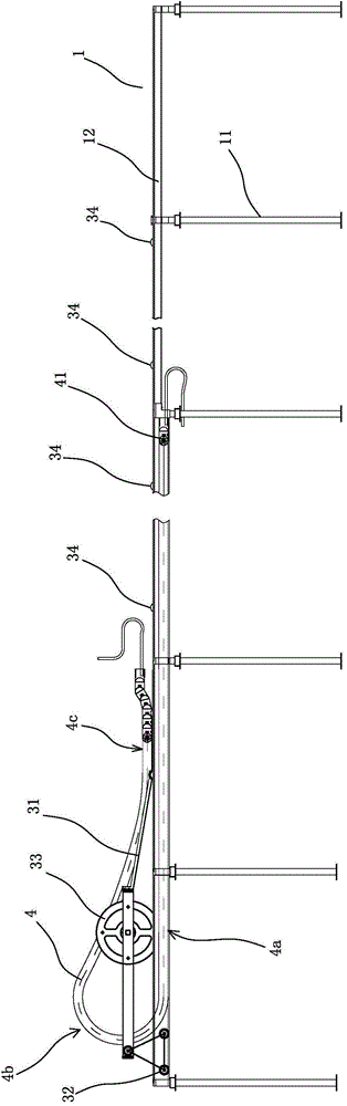
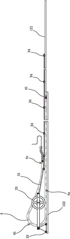
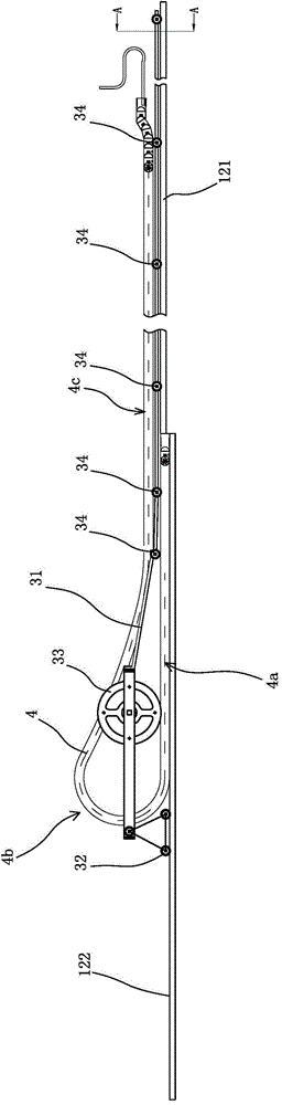
[0026] refer to Figure 1 to Figure 7 As shown, a long-distance heavy-duty drag chain supporting device includes a supporting frame 1 and a supporting mechanism.

[0027] The support frame 1 is provided with two first guide rails 122 extending horizontally and two second guide rails 121 extending horizontally. The first guide rails 122 extend from one end of the support frame 1 to the fixed end 41 of the drag chain 4. The second guide rails 121 extends from the fixed end 41 of the drag chain 4 to the other end of the support frame 1. The specific support frame 1 is composed of several support feet arranged at intervals in the transverse direction and two guard plates 12 bridged between two adjacent support legs. The plate 12 extends horizontally along the transverse direction and is arranged symmetrically. A guide groove for accommodating the drag chain 4 is formed between the two guard plates 12 . Both ends are fixed on the support beam 13, the guard plate 12 is composed of ...


PUM


Abstract

A long-distance heavy-load drag chain supporting device comprises a bearing frame used for bearing a drag chain and a supporting mechanism used for supporting the upper segment of the drag chain, wherein the bearing frame and the supporting mechanism horizontally extend in the transverse direction. The supporting mechanism comprises a supporting frame capable of being arranged on the bearing frame in a transversely moving mode, a plurality of supporting wheels arranged on the supporting frame at intervals and used for supporting the bottom of the upper segment of the drag chain, and a roller arranged on the supporting frame and located in a steering annular segment of the drag chain. When the steering annular segment of the drag chain moves transversely, the roller can be driven to transversely move, and thus the supporting frame is driven to transversely move and the upper segment of the drag chain is kept being supported by the supporting wheels. The long-distance heavy-load drag chain supporting device has the advantages of being simple in structure, high in adaptability, and capable of effectively preventing friction between the upper segment of the drag chain and the lower segment of the drag chain so that the service life of the drag chain can be prolonged.

Description

technical field [0001] The invention relates to the field of drag chains, in particular to a long-distance heavy-duty drag chain supporting device. Background technique [0002] The long-distance heavy-duty towline can be divided into three parts during the movement process, the lower section of the towline, the steering ring section of the towline and the upper section of the towline. The lower section of the towline is laid flat on the supporting frame of the towline. Due to the load, it is stacked on the top of the lower section of the towline, while the turning ring section of the towline forms a circular closed shape. Since the upper section of the towline is stacked on the lower section of the towline, the lower section of the towline will friction, the drag chain will be severely worn under heavy loads. For this reason, there are many solutions on the market, such as a full-stroke mobile support type heavy-duty drag chain disclosed by the publication number CN1587009A...

Claims


Application Information

Patent Timeline
Patent Type & Authority Applications(China)
IPC IPC(8): B65G39/20B65G23/04B65G17/38
Inventor 孙驰
Owner ZHEJIANG JINFULONG MACHINE TOOL ACCESSORIES
Why Eureka
Try Eureka