
A sweeping vehicle equipped with a wind guiding device

An air guiding device and sweeping vehicle technology, which is applied in the field of sweeping vehicles, can solve the problems of non-concentrated wind direction, damage to the filter element 15, and low efficiency of fan use, so as to achieve the effects of improving dust collection rate, preventing damage, and improving efficiency

Active Publication Date: 2017-05-03
FOSHAN GEMEI CLEANING EQUIP
View PDF9 Cites 0 Cited by
  • Summary
  • Abstract
  • Description
  • Claims
  • Application Information

AI Technical Summary

Problems solved by technology

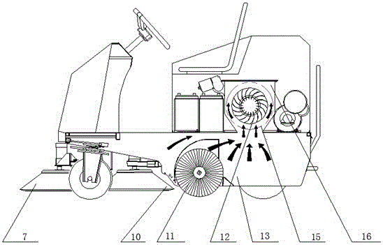
[0002] At present, in the same industry of sweeping vehicles, the dust raised during the sweeping process is collected through the dust box, and then processed, and the suction port of the sweeping vehicle is located just below the dust box, such as the patent "a kind of Dust-absorbing and sweeping vehicle” (Patent No. ZL200420099144.9), the position of the suction port of the sweeping vehicle is not equipped with any air guide device, resulting in ineffective dust collection and low fan efficiency. , the sweeper used, such as image 3 As shown by the arrow, let the suction wind suck the dust into the dust box 13 from any direction, so that the wind direction of the suction wind is not concentrated, resulting in an unsatisfactory effect of dust collection. This structure will cause the garbage thrown by the main brush to directly hit the filter element 15 in the dust box 13, which will cause direct damage to the filter element 15. At present, the technical problem affecting the installation of the air guiding device is that due to the accumulation left over from the filter element The dust should be cleaned frequently. After adding the air guide device, it will prevent the accumulated dust from falling into the vehicle garbage bin

Method used


Image

  • A sweeping vehicle equipped with a wind guiding device
  • A sweeping vehicle equipped with a wind guiding device
  • A sweeping vehicle equipped with a wind guiding device

Examples


Embodiment Construction

[0021] The accompanying drawings are for illustrative purposes only, and should not be construed as limitations on this patent; in order to better illustrate the present embodiment, some parts of the accompanying drawings may be omitted, enlarged or reduced, and do not represent the size of the actual product; for those skilled in the art It is understandable to the artisan that certain well-known structures and descriptions thereof may be omitted from the drawings.

[0022] In the description of the present invention, it should be noted that, unless otherwise expressly specified and limited, the terms "installation" and "connection" should be understood in a broad sense, for example, it may be a fixed connection, a detachable connection, or an integrated connection. It can be a mechanical connection or an electrical connection; it can be a direct connection or an indirect connection through an intermediate medium. It can be said that the two components are connected internally...


PUM


Abstract

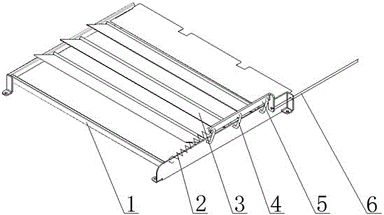
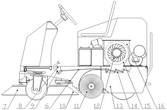
The invention relates to the field of cleaning and environment-friendly equipment, in particular to an air ducting device and a floor sweeping vehicle with the air ducting device. The air ducting device comprises a fixed base and a hinge set fixed on the fixed base, a hinge control switch for opening and closing the hinge set is connected to the hinge set, the hinge set comprises hinges and a hinge shaft, the hinges are connected to the hinge shaft, the front end of the hinge shaft is movably installed on one side of the fixed base, the tail end of the hinge shaft penetrates through the other side of the fixed base to be movably connected with the hinge control switch, a hinge synchronization plate is movably connected with the tail end of the hinge shaft, and the hinge control switch is fixed on the hinge synchronization plate. By means of the air ducting device and the floor sweeping vehicle with the air ducting device, suction air is generated by a draught fan, the front portion of a guide floor sweeping vehicle body is guided to mainly cause front brushing and middle brushing of raise dust, the suction air is concentrated, and damage of rubbish thrown up when a main brush sweeps the floor to a filter element can be further avoided.

Description

technical field [0001] The invention relates to the field of cleaning and environmental protection equipment, and more particularly, to an air guide device and a sweeper equipped with the air guide device. Background technique [0002] At present, in the same industry of sweepers, the dust raised during the sweeping process is collected through the dust box, and then processed. The vacuum cleaner (Patent No. ZL200420099144.9), the position of the suction port of the sweeper is not equipped with any air guide device, which leads to the insignificant effect of vacuuming and the low efficiency of the fan. At present, in the sweeper industry , using a sweeper such as image 3 As shown by the arrow of , let the suction wind suck the dust into the dust box 13 from any direction, so that the wind direction of the suction wind is not concentrated, which leads to the unsatisfactory effect of vacuuming. This structure will cause the garbage thrown up by the main brush to directly hit...

Claims


Application Information

Patent Timeline
Patent Type & Authority Patents(China)
IPC IPC(8): E01H1/08
Inventor 苏献
Owner FOSHAN GEMEI CLEANING EQUIP
Learn More