LED lamp tube

A technology of LED lamp tube and LED substrate, which is applied in the field of lighting, can solve the problems of affecting the light transmission effect, bending deformation of the lamp tube, poor heat dissipation effect, etc., and achieves firm and reliable fixing, not easy to bend and deform, and good use effect

Inactive Publication Date: 2014-10-08
SHENZHEN RUIFENG DISPLAY TECH
View PDF4 Cites 8 Cited by
  • Summary
  • Abstract
  • Description
  • Claims
  • Application Information

AI Technical Summary

Problems solved by technology

[0003] LED light tube is a common LED product that uses LED light source to realize lighting. LED light tube generally includes a lampshade and an LED substrate installed in the lampshade. As an important part of the LED light tube, the lampshade plays a role of light transmission and support. There are generally three types of existing LED lamp tubes. The first type is made of aluminum profile and PC cover, the second is full PC tube, and the third is glass tube. However, the structure of aluminum profile and PC cover is heavy. High cost and low safety; the full PC tube structure has low strength, and it is prone to problems such as bending and deformation of the lamp tube after long-term use, and the heat dissipation effect is poor; although the glass tube is strong and will not bend and deform, it passes through the The inner wall of the tube is sprayed with diffusion powder to achieve light transmission, and the diffusion powder is prone to unevenness or particles, which affects the light transmission effect. At the same time, because the glass tube cannot form the installation structure of the LED light board, the LED light board is bonded to the glass by glue In the tube, if used for a long time, it is prone to problems such as the LED light board falling off

Method used


Image

  • LED lamp tube
  • LED lamp tube
  • LED lamp tube

Examples


Embodiment Construction

[0024] The technical solution of the present invention will be described in detail below in conjunction with the accompanying drawings and specific embodiments, so as to understand the essence of the present invention more clearly and intuitively.

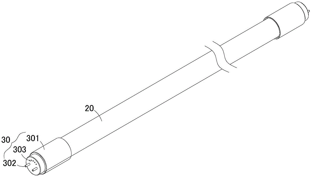
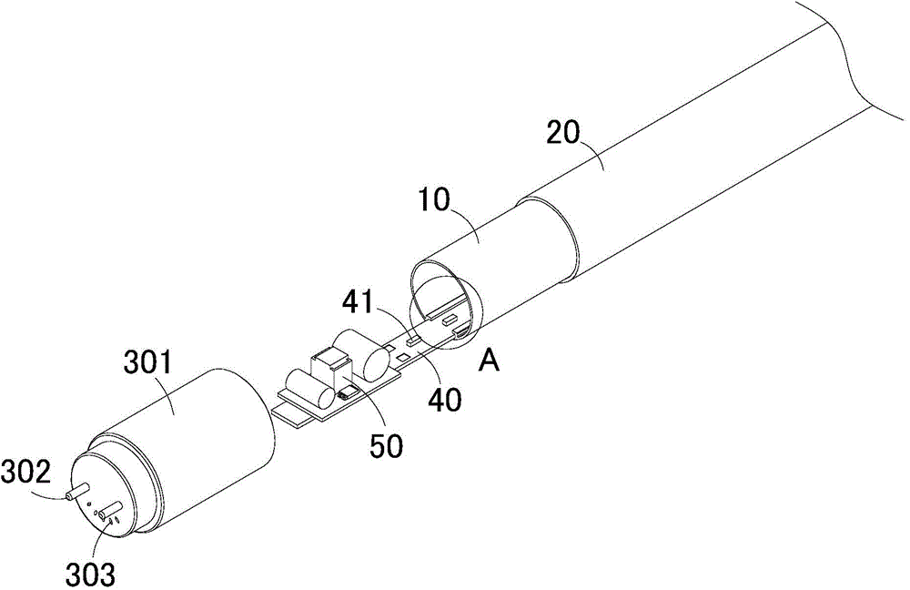
[0025] refer to Figure 1 to Figure 4 As shown, the present invention provides an LED lamp tube, which includes a plastic tube cover 10 , a glass tube 20 and two lamp caps 30 .

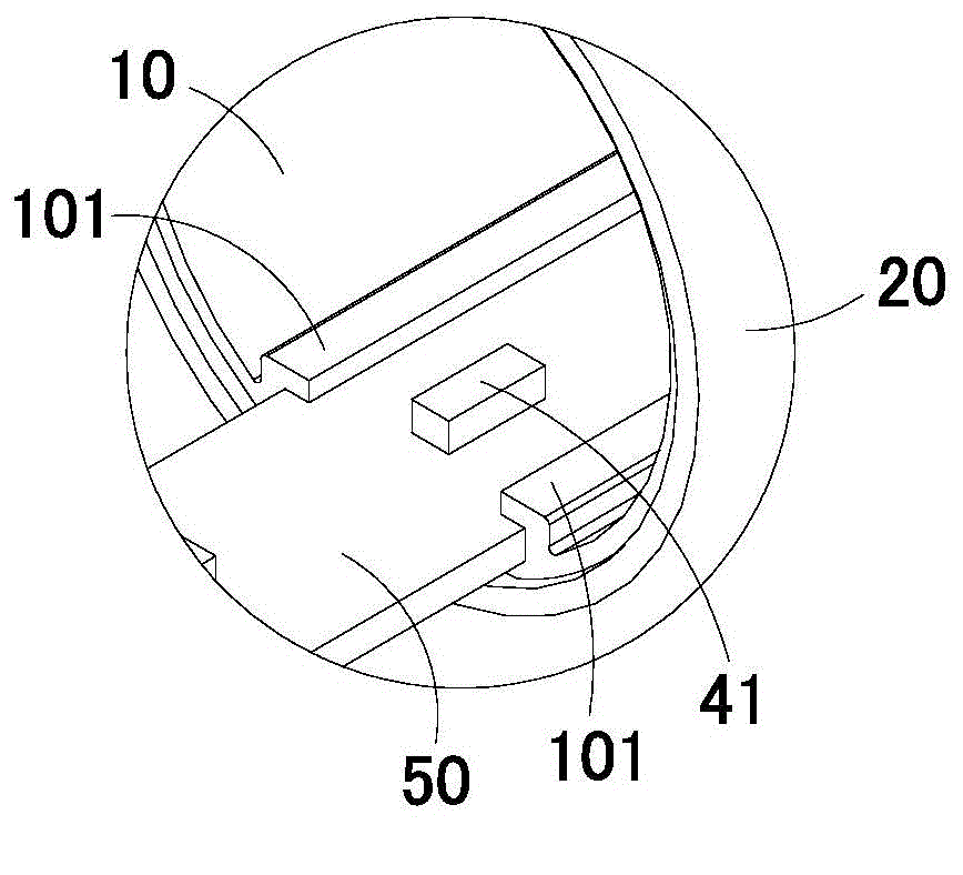
[0026] Specifically, the plastic pipe cover 10 can be a long strip tubular structure with a storage cavity extending in the axial direction. The LED substrate 40 is installed in the storage cavity. A plurality of LED light sources 41 are arranged on the LED substrate 40. The plurality of light sources Arranged in sequence along the length direction of the LED substrate 40 , since the LED light source 41 is used, the effect of energy saving and environmental protection can be achieved.

[0027] The glass tube 20 is sleeved on the outside of the plastic tub...


PUM


Abstract

The invention discloses an LED lamp tube which comprises a plastic tube cover, a glass tube and two lamp caps, wherein the plastic tube cover is provided with a containing cavity which can be stretched out and drawn back in the axial direction, an LED substrate is arranged in the containing cavity, and multiple LED light sources are arranged on the LED substrate; the plastic tube cover is sleeved with the glass tube, and the two lamp caps are arranged at the two ends of the glass tube respectively in a sleeved mode so as to seal the containing cavity. According to the LED lamp tube, the plastic tube cover is sleeved with the glass tube, so that on one hand the glass tube plays a role in supporting the plastic tube cover, the plastic tube cover cannot be bent to deform, and the use effect is better; on the other hand, under the support of the internal plastic tube cover, the glass tube is not prone to breakage, and even if the glass tube is broken, the whole LED lamp tube can be normally used as well; in addition, the glass tube can accelerate heat dissipation, and the heat dissipation effect of the whole LED lamp tube is improved.

Description

technical field [0001] The invention relates to the technical field of lighting, in particular to an LED lamp tube. Background technique [0002] With the development of optoelectronic technology, lighting products using LED as the light source are gradually introduced to the market, and LED is a cold light source. Compared with traditional incandescent lamps and fluorescent lamps, it has the advantages of energy saving, long life, impact resistance and not easy to break. , Compared with fluorescent lamps, it also has the advantages of no flickering, fast start-up speed, and no pollution to the environment. It has become a new generation of ideal light sources. Because LEDs have various advantages, LEDs have been widely used in various technical fields such as LED lighting. [0003] LED light tube is a common LED product that uses LED light source to realize lighting. LED light tube generally includes a lampshade and an LED substrate installed in the lampshade. As an importa...

Claims


Application Information

Patent Timeline
Patent Type & Authority Applications(China)
IPC IPC(8): F21S2/00F21V3/04F21V17/10F21Y101/02
Inventor 张胜刘小江张晓云
Owner SHENZHEN RUIFENG DISPLAY TECH
Why Eureka
Try Eureka