
Reclosing mechanism and method of leakage circuit breaker with clutch mechanism

A technology of leakage circuit breaker and clutch mechanism, applied in the direction of protection switch operation/release mechanism, etc., can solve problems such as increased production cost, influence of circuit breaker use, and difficulty in gear processing, and achieves the effect of reliable operation

Active Publication Date: 2016-06-08
EATON HUINENG LOW-VOLTAGE ELECTRICAL (JIANGSU) CO LTD
View PDF6 Cites 0 Cited by
  • Summary
  • Abstract
  • Description
  • Claims
  • Application Information

AI Technical Summary

Problems solved by technology

This reclosing mechanism has the following problems: 1. The gear is difficult to process, and the efficiency is relatively low, which increases the production cost
2. When installing, the component parts are not a whole structure, and cannot be installed as a whole set of components, and each circuit breaker mechanism needs to be adjusted separately
[0003] The Chinese patent application number is 2013102132814, and the name is "a reclosing mechanism for leakage circuit breakers". Two handle drivers are used. These two handle drivers respectively drive the circuit breaker to open and close, and are rigidly connected to the motor. Its defect is: in the process of tripping or opening and closing of the leakage circuit breaker, if the motor is powered off due to a fault, the handle of the leakage circuit breaker will not be manually operated, and the use of the circuit breaker will be affected

Method used


Image

  • Reclosing mechanism and method of leakage circuit breaker with clutch mechanism
  • Reclosing mechanism and method of leakage circuit breaker with clutch mechanism
  • Reclosing mechanism and method of leakage circuit breaker with clutch mechanism

Examples


Embodiment Construction

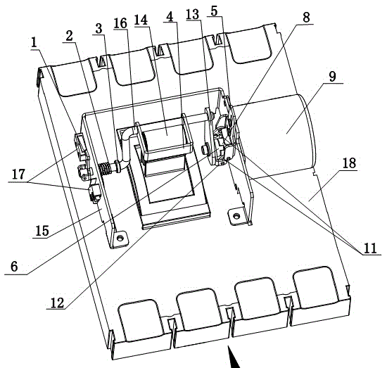
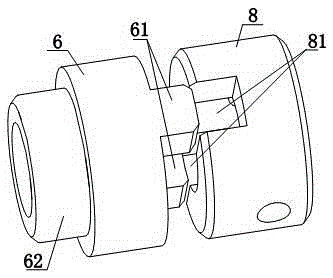
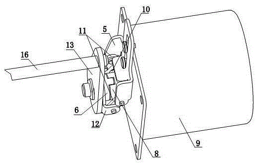
[0027] see Figure 1-3 As shown, the leakage circuit breaker itself has an outer cover 18 and a handle 14, the handle 14 is located in the middle of the circuit breaker outer cover 18 and the handle 14 protrudes upwards outside the circuit breaker outer cover 18, the handle 14 can be towards the circuit breaker inlet terminal or The direction of the outlet end is rotated, such as figure 1 The rear end in the middle is the incoming line end, and the front end is the outgoing line end. The present invention includes outer frame 15, connecting rod, rotating disk, driving lever, handle driver etc., outer frame 15 is fixedly installed on the outer cover 18, handle 14 is positioned between the left side wall of outer frame 15 and the right side wall during installation. A driving rod 16 is rotatably connected between the left side wall and the right side wall of the outer frame 15, the left end of the driving rod 16 is rotatably connected to the left side wall of the outer frame 15...


PUM


Abstract

The invention discloses a reclosing mechanism and a method for an earth leakage circuit breaker with a clutch mechanism. A return spring and a device for preventing the return spring from moving to the right end of the actuating lever are sleeved on the lever between the left side wall of the outer frame and the handle driver. Fixing parts; the left part of the axial clutch mechanism is empty with a third turntable located on the right side of the fixed end of the second connecting rod, and a moving plate that is movably connected with the right side wall of the outer frame is arranged above the right part of the axial clutch mechanism. Plate, the front side and the rear side of the moving plate are respectively connected to the front side and the rear side of the third turntable through a first connecting rod; the ejector rod runs through the right part of the axial clutch mechanism and the output shaft of the motor in the radial direction One end protrudes out of the right part of the axial clutch mechanism; press the moving plate downward, the third turntable moves to the left, the bottom of the moving plate touches the outer surface of the second turntable, and the ejector rod does not contact the bottom of the moving plate ; Electric operation and manual operation do not affect each other, ensuring reliable operation of the circuit breaker.

Description

technical field [0001] The invention relates to a molded case circuit breaker with residual current protection in the low-voltage electrical technical field, in particular to a reclosing mechanism of a leakage molded case circuit breaker with an automatic reclosing function. Background technique [0002] The leakage molded case circuit breaker with automatic reclosing function can ensure the continuous, safe and reliable operation of the power system. At present, the existing automatic reclosing mechanism of the molded case circuit breaker includes a handle, at least two large and small gears, a number of stamping parts and a number of standard parts. The motor is connected to the handle through the connecting rod on the eccentric wheel. The rod reciprocates to achieve the purpose of closing and opening the leakage circuit breaker. This reclosing mechanism has the following problems: 1. The gear is difficult to process, and the efficiency is relatively low, which increases ...

Claims


Application Information

Patent Timeline
Patent Type & Authority Patents(China)
IPC IPC(8): H01H71/10
Inventor 陈咸李冰燕严丽君
Owner EATON HUINENG LOW-VOLTAGE ELECTRICAL (JIANGSU) CO LTD
Learn More