Leakage protector

A technology of leakage protector and handle, which is applied in protection switch, emergency protection device, parts of protection switch, etc. It can solve the problems that the accuracy of tripping time cannot be guaranteed, installation is inconvenient, and the design of tripping mechanism is not compact.

Active Publication Date: 2014-10-08
浙江能美电子科技有限公司
View PDF4 Cites 4 Cited by
  • Summary
  • Abstract
  • Description
  • Claims
  • Application Information

AI Technical Summary

Problems solved by technology

[0003] However, most of the existing leakage protection switches are embedded and installed in the junction box on the wall
The existing junction box is 86-type box, but in practical applications, sometimes there are different types of box, for example, 120-type, 118-type box, but the existing leakage protector is difficult to install, only one type can be installed It is still very inconvenient to change

Method used


Image

  • Leakage protector
  • Leakage protector
  • Leakage protector

Examples


Embodiment Construction

[0016] The present invention will be further described below in conjunction with the accompanying drawings.

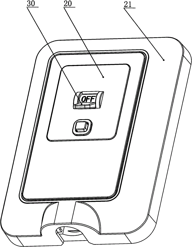
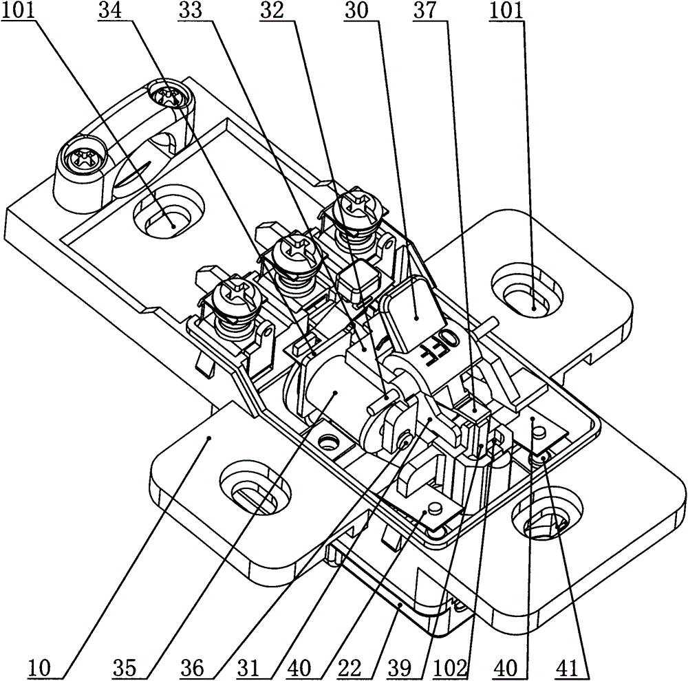
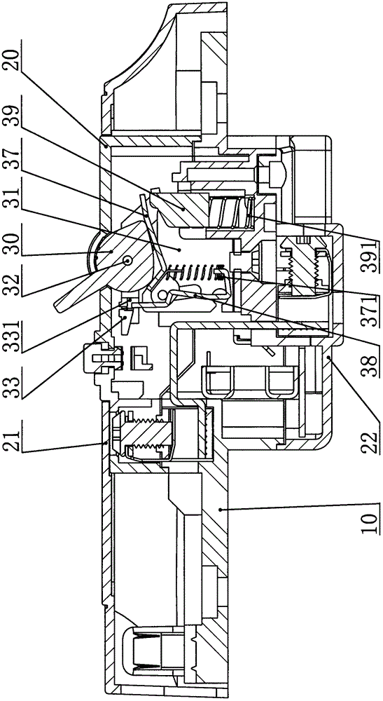
[0017] like figure 1 , 2 , 3, 4, 5, and 6, a leakage protector according to a specific embodiment of the present invention includes a base 10, a cover disposed on the upper end surface of the base 10, and the cover includes an upper cover 20 and a cover 21. The bottom cover 20 set on the lower end surface of the base 10, and the release mechanism set on the base 10, the base 10 is in the shape of a cross, and corresponding to the upper, lower, left and right ends of the base 10 are provided with waist-shaped Mounting hole 101. A plurality of waist-shaped mounting holes 101 are provided on the base 10, so that the earth leakage protector can be adapted to cassettes of various specifications. The tripping mechanism includes a bracket 31 arranged on the base 10, a bobbin 34 fixed on one side of the bracket 31, a positioning shaft 32 arranged on the upper end of the bra...


PUM


Abstract

The invention relates to a leakage protector which comprises a base, a cover body and a tripping mechanism. The tripping mechanism comprises a support, a coil frame, a positioning shaft, a handle, a jumping pin, a tripping component, two movable contacts on the base, static contacts which are arranged on the base and correspond to the contact ends of the movable contacts, and a contact frame device which is arranged in a mounting groove of the base and can drive the two movable contacts to move. The tripping component comprises a re-trip part and a lock catch which is linkage fit with the re-trip part, a spring is arranged between the re-trip part and the lock catch, the re-trip part is arranged at the lower end of the handle, and is in linkage fit with the handle, and a corresponding limiting groove is formed in the fit end of the jumping pin and the lock catch. An iron core is arranged on the coil frame, a coil is arranged on the iron core, one end of the iron core is fixed to one side of the jumping pin, and the iron core can drive the jumping pin to rotate around the positioning shaft. The protector has the advantages of being simple and compact in structure, and having the high sensitivity and rapid motion in reaction electric shock and leakage protection.

Description

technical field [0001] The invention relates to the field of leakage protection, in particular to a leakage protector. Background technique [0002] At present, the existing domestic building electrical connections are mostly connected by sockets, that is, the sockets are plugged into the conduction work. This kind of structural design is basically limited to the use of the current range below 16A, but in actual life, most of them exceed For the load equipment required by this current range, since there is a lack of wire-type leakage protection sockets exceeding the current range of 16A or more on the market, only wire-type leakage protection sockets below 16A can be used instead, but it is very easy to overload and cause electrical accidents. , resulting in personal safety accidents and economic losses. Therefore, the market is in urgent need of a wiring type leakage protector for buildings with a current range above 16A. Leakage protectors are mainly used to quickly cut ...

Claims


Application Information

Patent Timeline
IPC IPC(8): H01H71/24H01H71/02
Inventor 林忠生黄磊磊
Owner 浙江能美电子科技有限公司
Why Eureka
Try Eureka