Method for pulling in restoration pipe, and restored pipeline

A technology for repairing pipes and inspection holes, which is applied in the sewer pipeline system, pipeline laying and maintenance, pipes/pipe joints/pipe fittings, etc., and can solve problems such as reduced load bearing capacity, road subsidence, and insufficient drainage capacity

Active Publication Date: 2014-10-08
KANA FURETSUKUSU KOOHOREESHON
View PDF6 Cites 4 Cited by
  • Summary
  • Abstract
  • Description
  • Claims
  • Application Information

AI Technical Summary

Problems solved by technology

[0002] The sewer pipes buried in the soil for a long time may reduce the load bearing capacity and cause road subsidence or insufficient drainage capacity.

Method used


Image

  • Method for pulling in restoration pipe, and restored pipeline
  • Method for pulling in restoration pipe, and restored pipeline
  • Method for pulling in restoration pipe, and restored pipeline

Examples


Embodiment approach 1

[0061] Hereinafter, the present invention will be described in detail based on the embodiments shown in the drawings.

[0062] [1] Inspection of drainage channels

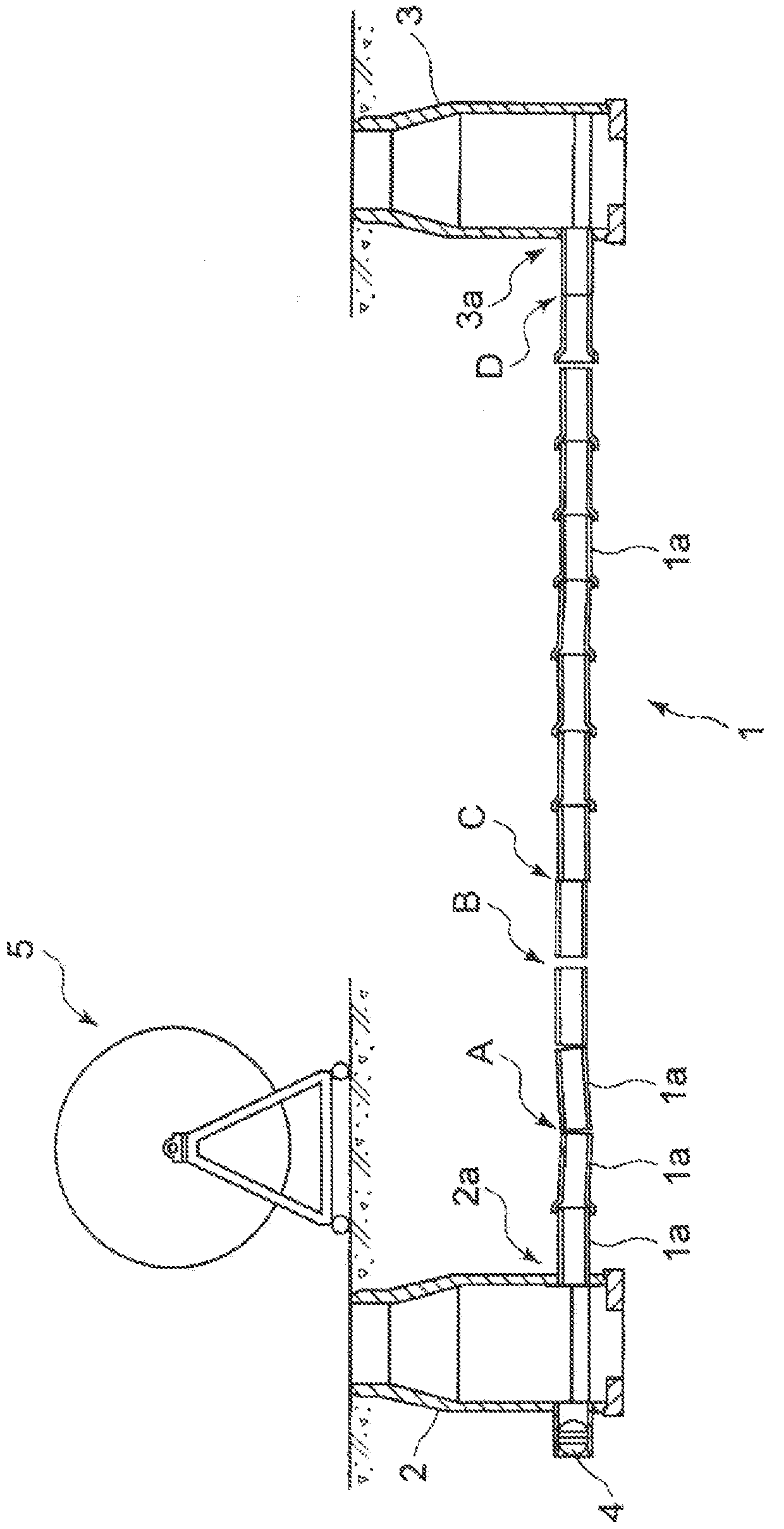
[0063] figure 1 It shows a deteriorating piped drainage channel to which the repairing pipe introduction method of the present invention is applied.

[0064] figure 1 Among them, the drainage channel 1 is formed by connecting a plurality of concrete drainage pipes 1 a and burying them in soil. One end of the drain passage 1 is connected to, for example, a lower opening 2 a provided at a lower portion of the upstream manhole 2 . The other end of the drain passage 1 is connected to a lower opening 3 a provided at a lower portion of the downstream manhole 3 .

[0065] When repairing the above-mentioned drainage channel 1, the inspection of the drainage channel 1 is carried out first.

[0066] Specifically, a high-pressure cleaning vehicle is placed, and the inside of the drainage channel 1 to be repaired is cle...

Deformed example 1

[0157] In Modification 1, the diagnosis process and the excavation process are performed before the simulation introduction process of the first embodiment.

[0158] In the diagnosis step, a diagnostic tool, which will be described later, is passed through the drainage channel 1 in order to detect a narrow portion in the drainage channel 1 . In addition, in the diagnostic process, it is preferable to insert a camera from behind the diagnostic tool, and to operate while checking the passing state of the diagnostic tool.

[0159] In the excavation step, an excavator is inserted into a narrow portion in the drain passage 1 detected in the diagnosis step, and the inner wall of the drain passage 1 is cut to expand the narrow portion.

[0160] [1]Diagnostic tool

[0161] Figure 11 It is an external view of a diagnostic tool 60 according to Modification 1. FIG. Figure 11 Among them, the diagnostic tool 60 of Modification 1 has a tool body 61 made of a metal member made of iron o...

Embodiment approach 2

[0187] [1] Inspection of drainage channels

[0188] Figure 13 It represents a deteriorating piped drainage channel to which the pipeline repair method of the present invention is applied.

[0189] Figure 13 Among them, the drainage channel 201 is formed by connecting a plurality of concrete drainage pipes 201a and burying them in soil. One end of the drain passage 201 is connected to, for example, a lower opening 202 a provided below the most upstream manhole 202 . The other end of the drain passage 201 is connected to a lower opening 203a provided below the manhole 203 on the downstream side.

[0190] When repairing the above-mentioned drainage channel 201, the inspection of the drainage channel 201 is performed first.

[0191] Specifically, a high-pressure cleaning vehicle is arranged near the manhole 203 on the downstream side, and the inside of the drainage channel 201 is cleaned with high-pressure water (cleaning step).

[0192] Next, a self-propelled camera (not s...


PUM


Abstract

Provided is a method for pulling in a restoration pipe that makes it easy to assess whether a restoration pipe with the largest possible diameter can be pulled into an aging drainage channel, and that enables the restoration pipe to be pulled in through a gap that is smaller than a sewer pipe. This method for pulling in a restoration pipe involves: preparing a dummy restoration pipe (30') that simulates a restoration pipe; attaching, to the insertion-side tip of the dummy restoration pipe (30'), an assessment jig (10) for assessing whether a restoration pipe can be pulled in; pulling the assessment jig (10) with the dummy restoration pipe (30') into an existing pipe (1); confirming that the assessment jig (10) with the dummy restoration pipe (30') has passed all the way through; and then attaching a pull-in jig to the tip of a restoration pipe, inserting the pull-in jig with the restoration pipe into the existing pipe (1) from a top opening (2b) of the existing pipe, and pulling the pull-in jig with a wire, thereby positioning the restoration pipe along the entire length of the existing pipe.

Description

technical field [0001] The present invention relates to existing pipes that have been cracked, damaged, or watertight at pipe joints lowered due to repeated application of loads caused by vehicle driving, earth pressure, or earthquake vibrations, etc., after a long period of time after being buried underground. Introduce a new resin-made repair tube, and repair the existing repair tube introduction method. Background technique [0002] If the sewer pipes are buried in the soil for a long time, the load bearing capacity will be lowered, resulting in road subsidence or insufficient drainage capacity. [0003] Patent Documents 1 and 2 disclose methods and devices for solving such problems. [0004] Figure 17 In the drainpipe repairing device described in Patent Document 1 shown, a new drainpipe made of resin is formed inside a deteriorated sewer pipe. According to the above-mentioned drainage pipe repairing device, the pipe body can be easily formed in the existing pipe with...

Claims


Application Information

Patent Timeline
Patent Type & Authority Applications(China)
IPC IPC(8): E03F7/00F16L1/00
CPCF16L55/1652E03F2003/065F16L55/18E03F7/00
Inventor 金尾茂树
Owner KANA FURETSUKUSU KOOHOREESHON
Why Eureka
Try Eureka