High-pressure fuel supply pump with electromagnetically driven suction valve

A technology of high-pressure fuel and electromagnetic drive, which is applied in the direction of fuel injection pumps, fuel injection devices, liquid fuel engines, etc., and can solve problems such as the enlargement of the electromagnetic drive mechanism, excessive sound generation, and the inability to reduce the holding current of the electromagnetic drive mechanism.

Active Publication Date: 2016-11-09
HITACHI ASTEMO LTD
View PDF5 Cites 0 Cited by
  • Summary
  • Abstract
  • Description
  • Claims
  • Application Information

AI Technical Summary

Problems solved by technology

When the fluid force of the recirculating fuel flow increases due to the increase in capacity, a correspondingly large electromagnetic force is required to maintain the valve open state without being affected by the fluid force, and there is a problem that the electromagnetic drive mechanism becomes larger.
If the standpoint is changed, there is also the following problem: when the fluid force acting on the valve member in the valve closing direction becomes larger than the magnetic attraction force at an unexpected moment, the valve member becomes closed in contact with the suction valve seat. Valve status, inability to perform accurate flow control, or inability to reduce the holding current after the starting current of the electromagnetic drive mechanism
[0011] In addition, in the electromagnetically driven suction valve mechanism described in the latter patent document, when the suction valve member is in the fully open valve state, there is a problem that it collides with the flapper to generate noise.
In the electromagnetic drive type suction valve mechanism of this patent document, the collision sound of the plunger and the restricting member, the collision sound of the armature (anchor) provided on the plunger rod and the fixed core, the front end of the plunger rod and the suction valve are generated. There is a problem that there are many sound generating parts due to the collision sound of components

Method used


Image

  • High-pressure fuel supply pump with electromagnetically driven suction valve
  • High-pressure fuel supply pump with electromagnetically driven suction valve
  • High-pressure fuel supply pump with electromagnetically driven suction valve

Examples


Embodiment Construction

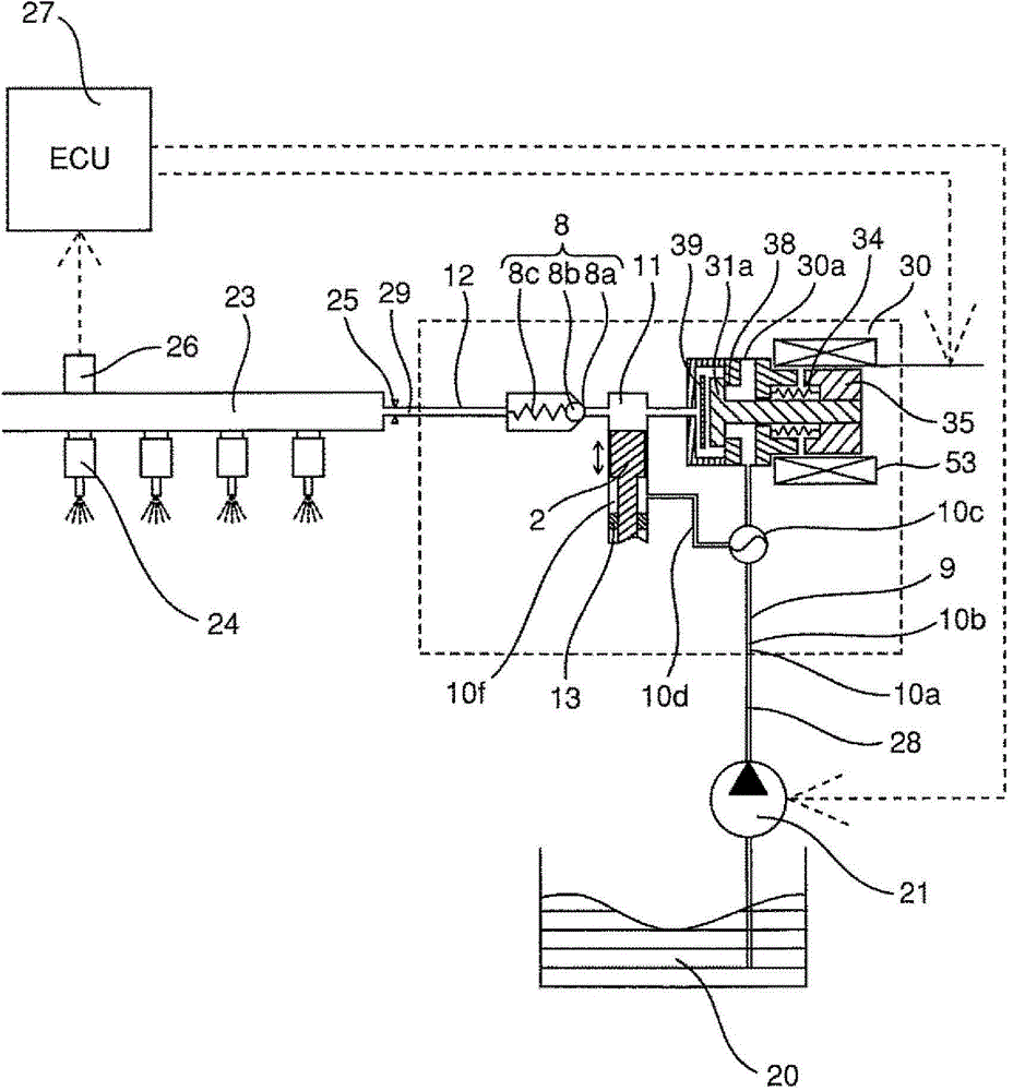
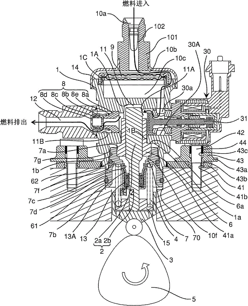
[0025] Below, based on Figure 1 to Figure 8 One embodiment of the high-pressure fuel supply pump including the electromagnetically driven suction valve of the present invention will be described.

[0026] The electromagnetically driven suction valve mechanism of the high-pressure fuel supply pump of this embodiment is configured as follows.

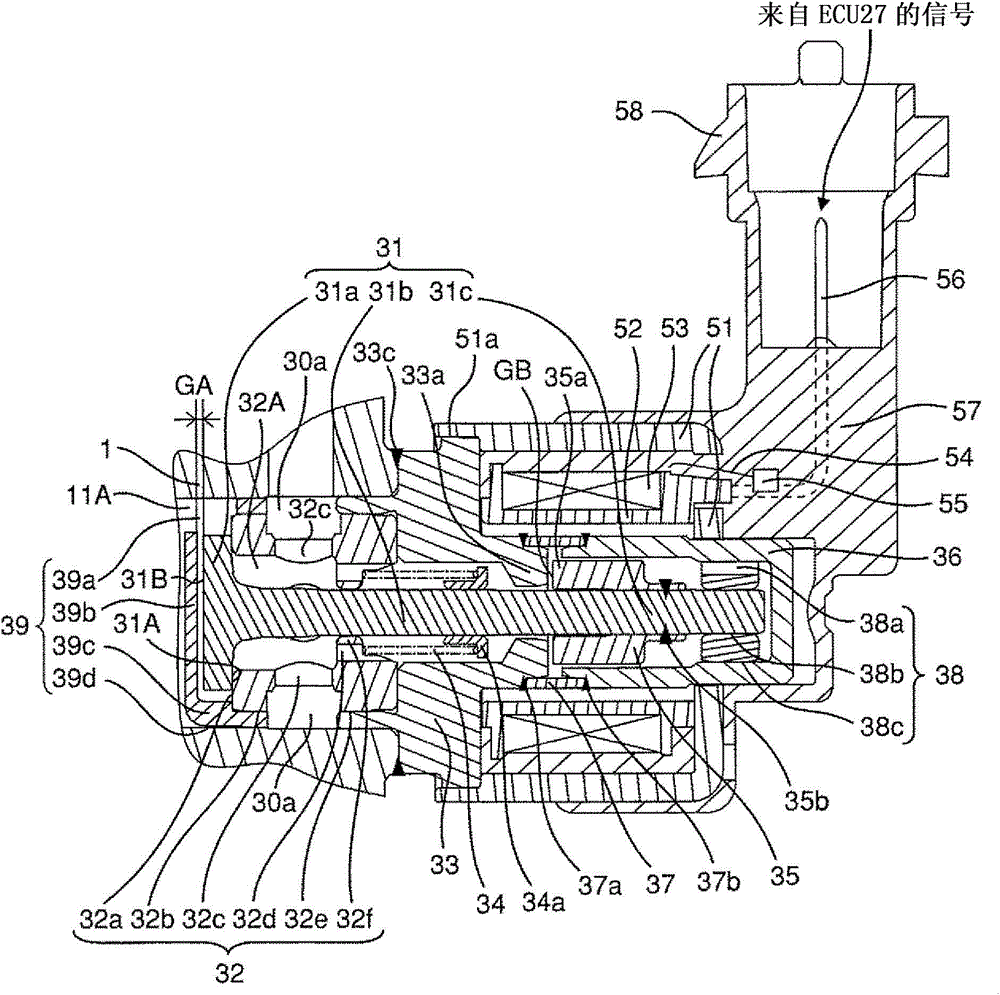
[0027] This electromagnetically driven suction valve mechanism is a so-called normally closed type, in which a valve member 31a and a plunger rod 31b are integrated, and a spring 34 biasing the plunger rod 31b biases the valve member 31a in the valve closing direction.

[0028] This electromagnetically driven suction valve mechanism has a plunger rod 31 b that is operated by an electromagnetic force generated by an electromagnetic coil 53 . The armature 35 fixed to the armature fixing portion 31 c of the plunger rod 31 b approaches the fixed iron core 33 by electromagnetic force, and collides with the end surface of the fixed iron core ...


PUM


Abstract

The present invention provides a high-pressure fuel supply pump equipped with a normally closed electromagnetically driven suction valve mechanism suitable for increasing the capacity and generating less sound. This high-pressure fuel supply pump equipped with an electromagnetically driven suction valve mechanism includes: a valve member having a valve seat surface abutting against a suction valve seat; and a plunger rod positioned on the valve seat surface side of the valve member and magnetically attracted When the plunger rod moves the entire stroke in the valve opening direction of the valve member and the armature for driving the plunger rod comes into contact with the stopper, the shield is in contact with the valve member. Surfaces on the opposite side to the valve seat surface are arranged to face each other with a gap therebetween. Accordingly, it is possible to reduce the fluid force that urges the valve member in the valve-closing direction on the surface of the valve member opposite to the valve seat surface due to the fuel overflowing from the pressurization chamber. In addition, since the shield and the suction valve member are not in contact, there is no increase in sound generation. Therefore, it is possible to provide a high-pressure fuel supply pump that can accurately control the flow rate and reduce the generation of sound even if the capacity is increased.

Description

technical field [0001] The present invention relates to a high-pressure fuel supply pump used in an in-cylinder injection type internal combustion engine and provided with an electromagnetically driven suction valve mechanism, and more particularly to a high-pressure fuel supply pump provided with an electromagnetically driven suction valve mechanism as follows, The electromagnetically driven suction valve mechanism described above is a so-called normally closed electromagnetically driven suction valve in which the valve member and the plunger rod are integrated, and the spring biasing the plunger rod biases the valve member in the valve closing direction. mechanism. Background technique [0002] In the high-pressure fuel supply pump provided with the electromagnetically driven suction valve mechanism described in Japanese Patent Application Laid-Open No. 2006-250086, the movable plunger operated by electromagnetic force of the electromagnetically driven suction valve mechan...

Claims


Application Information

Patent Timeline
Patent Type & Authority Patents(China)
IPC IPC(8): F02M59/36F02M51/00F02M59/20F02M59/44F02M59/46F16K31/06
CPCF02M59/44F02M59/466F04B1/0439F04B1/0456F04B53/1082F02M59/36F02M51/00F02M59/20F02M59/46F02M51/04F04B7/0076
Inventor 臼井悟史河野达夫山田裕之宫崎胜巳岩仓健太桥田稔
Owner HITACHI ASTEMO LTD
Why Eureka
Try Eureka