A Composite Profile Outer Frame Structure for Sillless Doors and Windows

A composite profile, no threshold door technology, applied in the direction of window/door frame, etc., can solve the problems of complex process requirements, moisture, wood corrosion, etc.

A composite profile, no threshold door technology, applied in the direction of window/door frame, etc., can solve the problems of complex process requirements, moisture, wood corrosion, etc.

CN104100170BActive Publication Date: 2016-08-24浙江瑞明节能门窗技术有限公司

Image

  • A Composite Profile Outer Frame Structure for Sillless Doors and Windows
  • A Composite Profile Outer Frame Structure for Sillless Doors and Windows

Examples


Embodiment Construction

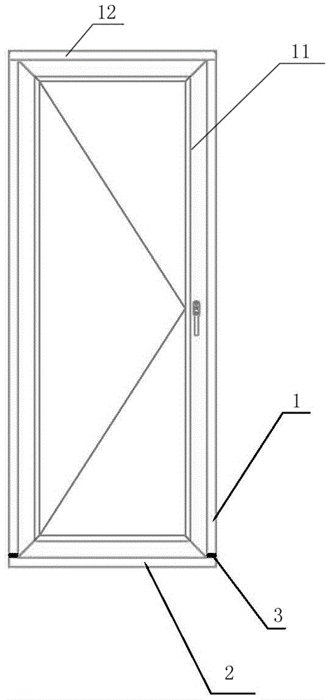
[0009] The present invention will be described in detail below in conjunction with accompanying drawing: figure 1 As shown, a composite profile frame group structure of doors and windows without sills, the outer frame 11 is assembled from the left and right vertical frames 1, the upper door frame 12 and the lower door frame, and the lower door frame is a door frame without sills 2. The lower ends of the left and right vertical frames 1 are placed on the upper parts of both ends of the sill-free door frame 2, and the lower end of the vertical frame 1 and the upper end of the sill-free door frame are at least connected together by a sill-free door spacer 3 The two ends of the upper door frame 12 are respectively connected to the upper ends of the left and right vertical frames by means of a 45-degree angle or a 90-degree connection.

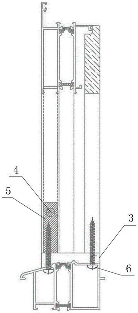
[0010] figure 2 As shown, the vertical frame 1 is an aluminum-wood composite frame composed of an outer aluminum alloy profile and an inner wood...


PUM


Abstract

A composite profile outer frame group frame structure for doors and windows without sills, the outer frame is assembled from left and right vertical frames, an upper door frame and a lower door frame, the lower door frame is a door frame without sills, and the left and right vertical frames are assembled. The lower end of the frame is placed on the upper part of the two ends of the door frame without sill, and the lower end of the vertical frame and the upper edge of the end of the door frame without sill are connected together by at least a door pad without sill; the two ends of the upper door frame are respectively It is connected with the upper ends of the left and right vertical frames by a 45-degree angle or a 90-degree connection; it simplifies the form of the frame between the two and simplifies the production process requirements. The direct contact between the vertical frame and the door frame without sills protects the wood at the bottom of the vertical frame from being attacked and corroded by moisture.

Description

technical field [0001] The invention relates to a composite profile outer frame group structure for doors and windows without sills, and belongs to the technical field of building door and window structures. Background technique [0002] In the prior art, for doors and windows with sillless door structure design, because the design of the bottom sill is different from other frame materials, the frame structure of the lower opening is different from that of the upper opening; The sills are connected by milling and reverse type, which requires complex process and difficult production; and when there is wooden material on the frame profile, the end face of the wooden profile at the lower opening of the mullion, where it directly contacts the sill, is easy to absorb water, Moisture, which in turn causes problems such as wood corrosion. Contents of the invention [0003] The purpose of the present invention is to overcome the deficiencies in the prior art, and to provide a non...

Claims


Application Information

Patent Timeline
24 Aug 2016
Publication
CN104100170B
IPC
E06B1/32
Inventors
余亮; 潘昌平