Vacuum actuator, engine intake manifold flap control device and engine

A vacuum actuator, intake manifold technology, applied in engine control, machine/engine, fuel air intake, etc., can solve problems such as incorrect control of push rod intake manifold flaps

Active Publication Date: 2014-10-15
BEIJING BORGWARD AUTOMOBILE CO LTD
View PDF7 Cites 2 Cited by
  • Summary
  • Abstract
  • Description
  • Claims
  • Application Information

AI Technical Summary

Problems solved by technology

However, there is a problem in the prior art: when the push rod driven by the vacuum actuator fails or wears out, the control unit will make an error in the control of the intake manifold flap.

Method used


Image

  • Vacuum actuator, engine intake manifold flap control device and engine
  • Vacuum actuator, engine intake manifold flap control device and engine
  • Vacuum actuator, engine intake manifold flap control device and engine

Examples


Embodiment Construction

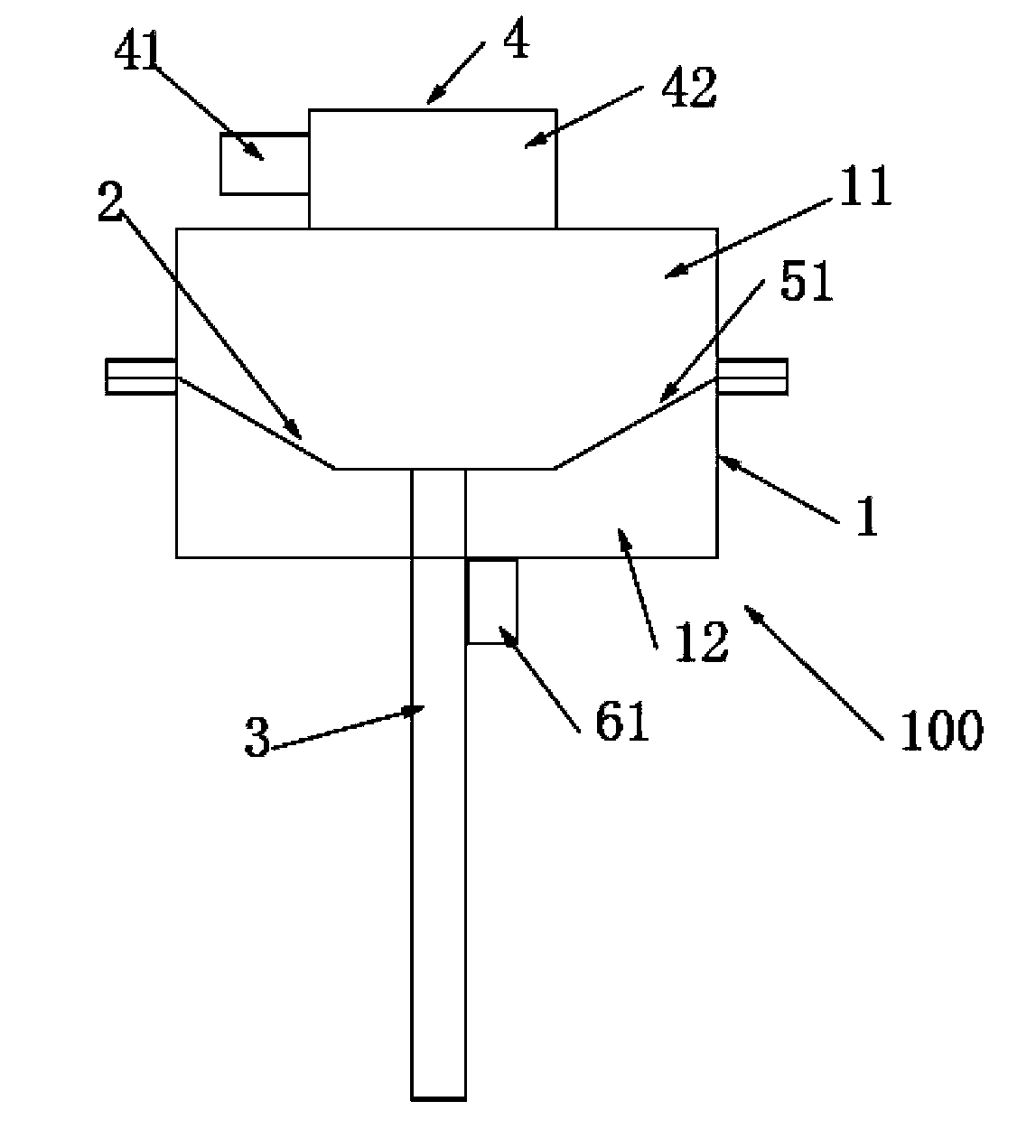
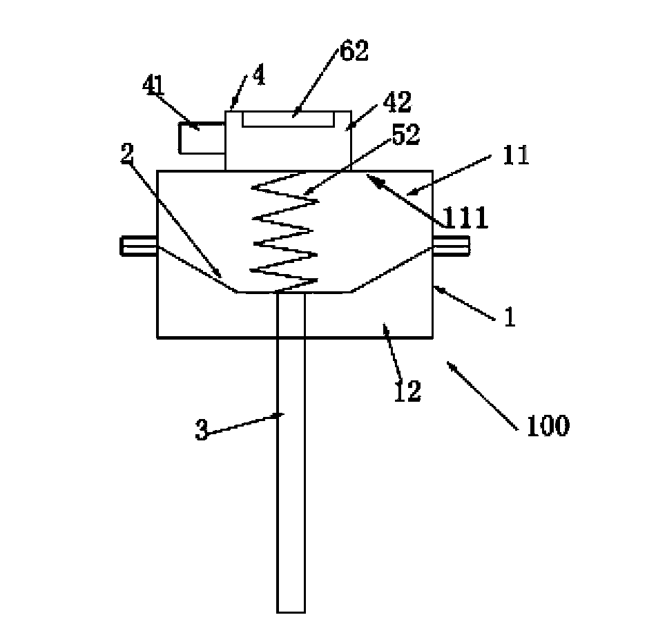
[0027] Embodiments of the present invention are described in detail below, examples of which are shown in the drawings, wherein the same or similar reference numerals designate the same or similar elements or elements having the same or similar functions throughout. The embodiments described below by referring to the figures are exemplary only for explaining the present invention and should not be construed as limiting the present invention.

[0028] In describing the present invention, it should be understood that the terms "center", "longitudinal", "transverse", "upper", "lower", "front", "rear", "left", "right", " The orientations or positional relationships indicated by "vertical", "horizontal", "top", "bottom", "inner" and "outer" are based on the orientations or positional relationships shown in the drawings, and are only for the convenience of describing the present invention and Simplified descriptions, rather than indicating or implying that the device or element refe...


PUM


Abstract

The invention discloses a vacuum actuator used for an engine intake manifold flap control device. The vacuum actuator comprises a cavity, a diaphragm, a push rod, a reset device, an air inlet unit and a push rod position detection device, wherein the diaphragm is arranged in the cavity to divide the cavity into an upper cavity and a lower cavity; one end of the push rod passes through the lower cavity so as to be connected with the diaphragm, and the other end of the push rod is used for pushing an engine intake manifold flap; the reset device is used for resetting the diaphragm; the air inlet unit is communicated with the upper cavity, so that the diaphragm is pushed by gas entering the upper cavity; the push rod position detection device is used for detecting the movement distance of the push rod. According to the vacuum actuator disclosed by the embodiment of the invention, the phenomenon that control performed on the intake manifold flap by a control unit goes wrong due to the fact that the push rod breaks down or is abraded and the like can be avoided. The invention further discloses the engine intake manifold flap control device and an engine comprising the same.

Description

technical field [0001] The invention relates to an engine, in particular to a vacuum actuator, an engine intake manifold flap control device and an engine with the same. Background technique [0002] Most of the existing direct-injection engines adopt stratified combustion technology. In order to meet various charging modes, an intake manifold flap control system is introduced. When the engine is in low-speed working condition and adopts the stratified charging mode, the intake manifold flap closes the lower intake passage to form a narrower cross-sectional area, which increases the airflow velocity and effectively forms a strong intake vortex. It is conducive to the formation and atomization of the mixed gas in the stratified charge mode, which improves the combustion efficiency and increases the engine torque output; when the engine enters high-speed operating conditions and adopts the homogeneous mixed gas mode, the intake manifold flap passes through Open the lower air ...

Claims


Application Information

Patent Timeline
Patent Type & Authority Applications(China)
IPC IPC(8): F02D9/02F02M35/10
Inventor 刘婷武凤荣
Owner BEIJING BORGWARD AUTOMOBILE CO LTD
Why Eureka
Try Eureka