LED illuminating device with micro-structure optical film

A technology for LED lighting and optical films, which is applied to lighting devices, lighting device parts, lighting and heating equipment, etc., can solve the problems of increasing the cost of LED lighting devices, restricting wide application, and feeling glare to users, so as to meet lighting requirements. Light distribution, the effect of improving glare

Inactive Publication Date: 2014-10-15
中蓝光电科技(上海)股份有限公司
View PDF8 Cites 3 Cited by
  • Summary
  • Abstract
  • Description
  • Claims
  • Application Information

AI Technical Summary

Problems solved by technology

Therefore, when the LED light source changes, the secondary or multiple optical control devices designed for a certain LED cannot continue to be used. The secondary or multiple optical control devices have poor versatility and need to be redesigned and manufactured for secondary or multiple times Optical control devices, which greatly increase the cost of LED lighting devices, limiting the wide application of LEDs
[0005] In addition, due to the concentrated optical output of the LED light source, the surface brightness of the LED lighting device is very high, which makes the user feel very dazzling, and the glare is strong, which also restricts the wide application of LED

Method used


Image

  • LED illuminating device with micro-structure optical film
  • LED illuminating device with micro-structure optical film
  • LED illuminating device with micro-structure optical film

Examples


Embodiment Construction

[0019] The present invention will be further described in detail in conjunction with the following specific embodiments and accompanying drawings.

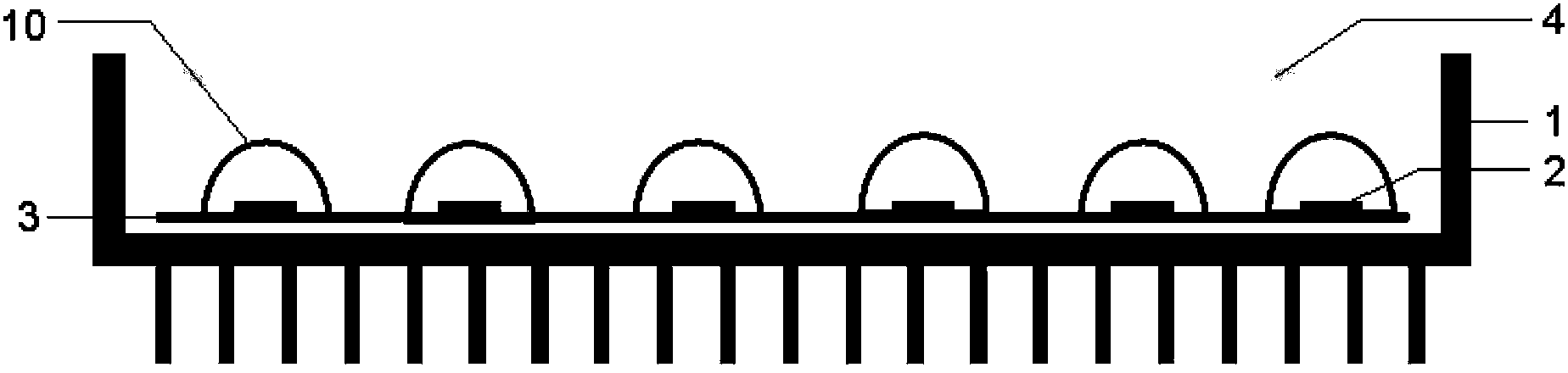
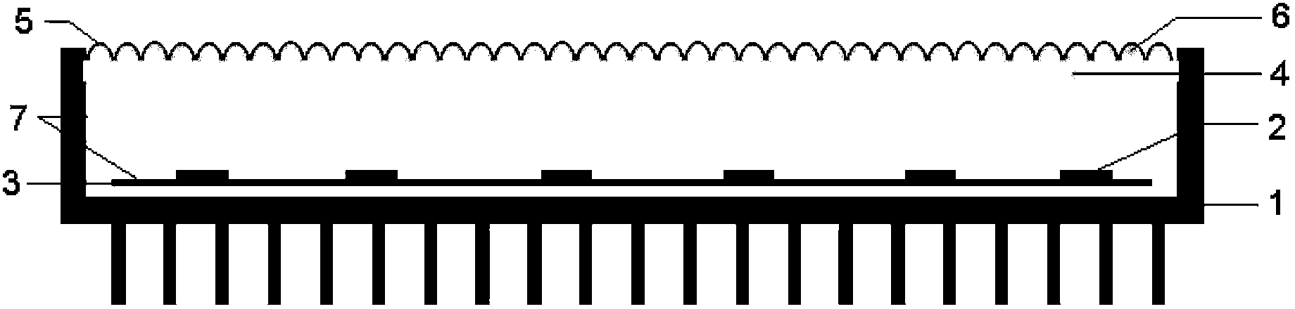
[0020] figure 2 Among them, 1 represents the casing, 2 represents the LED chip, 3 represents the printed circuit board, 4 represents the cover, 5 represents the microstructured optical film, 6 represents the protrusion, and 7 represents the reflective optical film.

[0021] Such as figure 2 As shown, the LED lighting device with a microstructured optical film of the present invention comprises: a casing 1, a printed circuit board (PCB) 3 arranged in the casing 1, at least one LED chip 2 arranged on the printed circuit board 3, and the LED chip 2. An LED drive power supply (not shown) that is electrically connected to drive the LED chip to emit light, and a cover 4 and a microstructured optical film 5 arranged above the LED chip to control the optical output of the LED chip 2 to meet the lighting requirements of a specific appli...


PUM


Abstract

The invention provides an LED (Light Emitting Diode) illuminating device with a micro-structure optical film. The LED illuminating device comprises a shell (1), a printed circuit board (3), at least one LED chip (2), an LED driving power supply and a cover (4), wherein the printed circuit board (3) is arranged in the shell (1); the LED chip (2) is arranged on the printed circuit board (3); the LED driving power supply is electrically connected with the LED chip (2); the cover (4) is used for packaging the LED chip in the shell (1); the LED illuminating device is characterized by further comprising the micro-structure optical film (5) arranged on the upper surface of the cover (4); the micro-structure optical film (5) is used for controlling the optical output of the LED light source so as to meet an illuminating demand of a specific application scene; the micro-structure optical film is utilized to adjust the concentrated optical output of the LED light source, so that the glare condition is effectively improved while the illuminating light distribution is met.

Description

technical field [0001] The invention relates to an LED lighting device, in particular to an LED lighting device with a microstructure optical film. Background technique [0002] Semiconductor photodiodes (LEDs, Light Emitting Diodes), as a new energy-saving and environmentally friendly light source, are more and more widely used in general lighting environments. Existing LEDs for lighting applications have the brightness, efficiency, service life, color temperature, and white point stability required for general lighting. As a result, these LEDs are used in the design of most general lighting applications, including pavement, parking areas, and indoor directional lighting. In these applications, LED-based lighting fixtures reduce the total cost of ownership (TCO) due to no maintenance (LEDs last much longer than conventional light bulbs) and low energy consumption. Illumination-grade LEDs have at least 50,000 hours of efficient, directional illumination. The lighting syst...

Claims


Application Information

Patent Timeline
Patent Type & Authority Applications(China)
IPC IPC(8): F21S2/00F21V5/04F21V5/02F21Y101/02
Inventor 甘雨洁
Owner 中蓝光电科技(上海)股份有限公司
Why Eureka
Try Eureka