thin heat pipe

一种薄型热管、管体的技术,应用在热管领域,能够解决薄型热管损坏、圆柱形热管难以设置、中央区域易产生凹陷等问题,达到增加强度的效果

Active Publication Date: 2017-02-08
WISTRON KUSN +1
View PDF7 Cites 0 Cited by
  • Summary
  • Abstract
  • Description
  • Claims
  • Application Information

AI Technical Summary

Problems solved by technology

However, the known cylindrical heat pipes are too thick to be installed in today's portable computers, so thin heat pipes need to be used instead
[0003] However, it is known that the width of the thin heat pipe is relatively wide and the thickness is relatively thin, so that the central area of ​​the thin heat pipe is prone to depression, resulting in damage to the thin heat pipe.
In addition, the capillary structure of the heating end of the thin heat pipe is insufficient, which causes the dry out phenomenon of the heating end of the heat pipe, which in turn affects the performance of the heat pipe

Method used


Image

  • thin heat pipe
  • thin heat pipe
  • thin heat pipe

Examples


Embodiment Construction

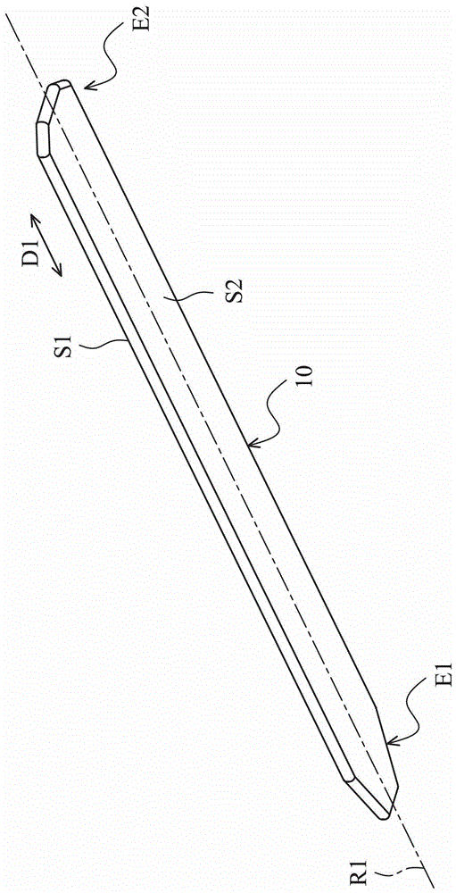
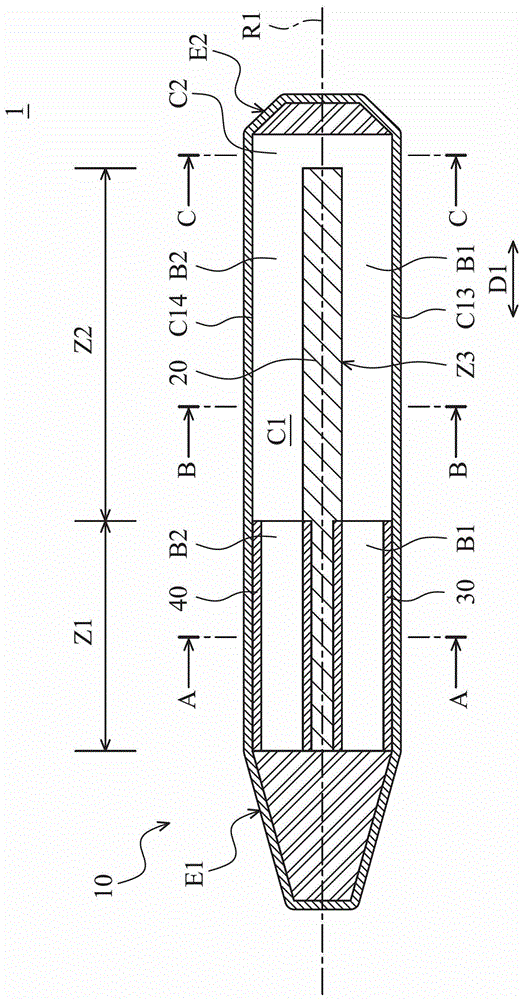
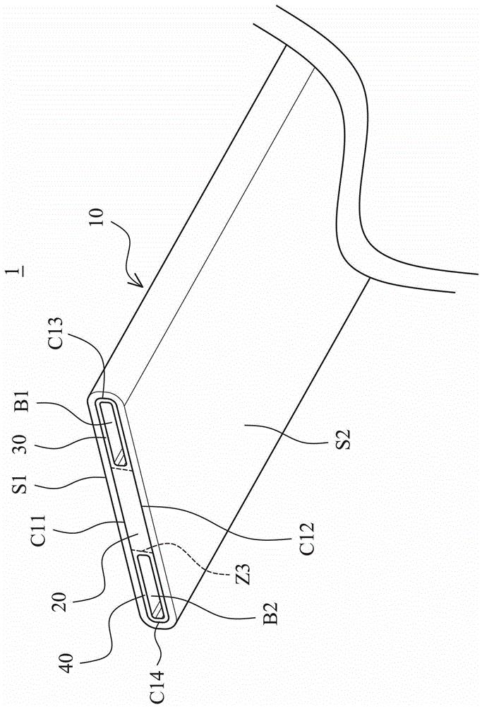
[0025] figure 1 It is a perspective view of the thin heat pipe 1 of the present invention, figure 2 It is a longitudinal sectional view of the thin heat pipe 1 of the present invention. The thin heat pipe 1 includes a pipe body 10 , a main capillary structure 20 , a first capillary structure 30 and a second capillary structure 40 . The tube body 10 is a flat sealing structure. The width of the pipe body 10 may be three times, four times, or more than five times the thickness of the pipe body 10 . The tube body 10 may have a first outer plane S1 and a second outer plane S2, and the first outer plane S1 is parallel to the second outer plane S2. The tube body 10 may include heat-conducting materials such as metal, and extends along an extending path R1. In this embodiment, the extension path R1 is a straight line and extends along an extension direction D1. In another embodiment, the extending path R1 may include a straight section and / or a curved section.

[0026] The tub...


PUM


Abstract

A thin heat pipe. The thin heat pipe includes a tube body, a main capillary structure, a first capillary structure and a second capillary structure; the tube body has a hollow cavity and a communication cavity communicating with the above-mentioned hollow cavity, and the above-mentioned hollow cavity extends along the extension path; the main capillary structure is arranged in the hollow cavity Inside and extending along the above-mentioned extension path; the first capillary structure is arranged on the side of the above-mentioned main capillary structure and has a first channel parallel to the above-mentioned extension path; the second capillary structure is arranged on the other opposite side of the above-mentioned main capillary structure, and has a parallel The second channel of the above-mentioned extension path; the above-mentioned communication cavity communicates with the above-mentioned first channel and the above-mentioned second channel; the above-mentioned main capillary structure is located between the above-mentioned first channel and the above-mentioned second channel; the above-mentioned hollow cavity has an upper surface and is opposite to the above-mentioned upper surface The lower surface of the surface, and the above-mentioned main capillary structure and the above-mentioned first and second capillary structures are arranged on the above-mentioned upper surface and the above-mentioned lower surface. The invention can increase the strength of the heat pipe and prevent the dry phenomenon of the heat pipe.

Description

technical field [0001] The present invention mainly relates to a heat pipe, especially a thin heat pipe. Background technique [0002] Currently, portable computers such as notebook computers and tablet computers are all developing toward thinning. However, the known cylindrical heat pipes are too thick to be installed in today's portable computers, so thin heat pipes need to be used instead. [0003] However, the known thin heat pipe has a wide width and a relatively thin thickness, so that the central area of ​​the thin heat pipe is prone to sag, resulting in damage to the thin heat pipe. In addition, the capillary structure of the heating end of the thin heat pipe is insufficient, which causes the phenomenon of dry out of the heating end of the heat pipe, thereby affecting the performance of the heat pipe. [0004] Therefore, it is necessary to provide a thin heat pipe to solve the above problems. Contents of the invention [0005] In order to solve the deficiencies ...

Claims


Application Information

Patent Timeline
Patent Type & Authority Patents(China)
IPC IPC(8): F28D15/04G06F1/20
CPCF28D15/0233F28D15/046
Inventor 张永利单建兵
Owner WISTRON KUSN
Why Eureka
Try Eureka