Device and methodpreventing drying in pipe

A stirring device and pipeline technology, which is applied in the field of grouting structural components, can solve the problems of less grouting pipe grout, poor sealing quality of the furnace cover, and insufficient grouting, etc., and achieves low equipment investment, convenient operation, and low cost Effect

Active Publication Date: 2019-01-15
SHANGHAI MEISHAN IRON & STEEL CO LTD
View PDF8 Cites 0 Cited by
  • Summary
  • Abstract
  • Description
  • Claims
  • Application Information

AI Technical Summary

Problems solved by technology

[0002] After the existing coke oven is filled with coal, environmental protection requires that the furnace cover and the furnace seat must be sealed to prevent the toxic gas and dust inside from overflowing. The current technology is to pour grout, and the grout with a certain viscosity dries up in a high temperature environment to form a solid , adhered between the furnace cover and the furnace seat to play a sealing role. At present, there are two ways of manual grouting and automatic mechanical equipment. Automatic grouting in the environment of poisonous gas and dust in the coke oven is promoted and used. It flows into the furnace cover and furnace seat through the pipeline. The slurry is made of powdered grout and water and stirred into a liquid state. After the water evaporates, it forms a block and adheres to the container. Therefore, the slurry adhered to the pipeline after a period of time after grouting The inside will become dry and gradually accumulate, the volume of the grouting pipe will become smaller, resulting in less grouting, and at the same time, it will dry up and block the holes on the grouting ring. At this time, the sealing quality of the furnace cover will be poor and there will be empty sections that cannot be grouted. Phenomenon

Method used


Image

  • Device and methodpreventing drying in pipe
  • Device and methodpreventing drying in pipe
  • Device and methodpreventing drying in pipe

Examples


Embodiment 1

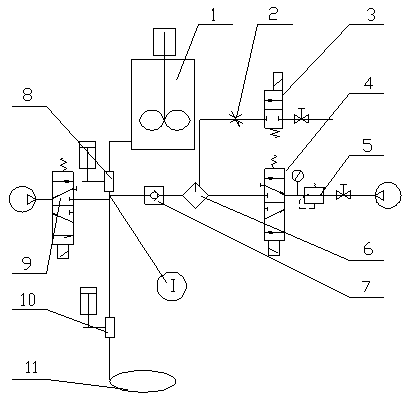
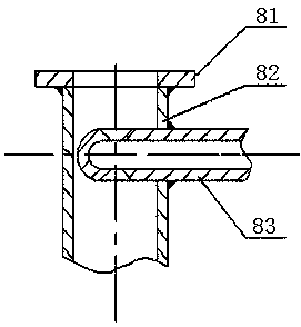
[0019] Embodiment 1: see Figure 1-Figure 3 , a device for preventing dryness in a pipe, the device includes an automatic grouting system and a control valve, the automatic grouting system includes a stirring device 1, a grouting ball valve 8, a grouting pneumatic reversing valve 9, and a grouting ball valve 10 And an annular grouting ring 11, the control valve includes a throttle valve 2, an electromagnetic water valve 3, a pneumatic reversing valve 4, a pressure reducing valve 5, a lubricator 6 and a one-way valve 7, and the stirring device passes through the pipeline Connect the grouting ball valve 8, the grouting ball valve 8 is connected to the grouting ball valve 10 and the annular grouting ring 11 through the pipeline, the one-way valve is sequentially connected to the throttle valve and the electromagnetic water valve through the lubricator, and the other way is sequentially Connect the pneumatic reversing valve and the pressure reducing valve. The lower flange 81, the...

Embodiment 2

[0020] Example 2: see Figure 1-Figure 4 , to prevent the method of drying in the tube, the method is as follows,

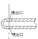
[0021] Step 1: Install the equipment, install the equipment needed to prevent the dry-out device in the coke oven automatic grouting pipeline into the automatic grouting equipment, install the nozzle pipe with a spray angle under the ball valve for discharging grout, and align the nozzle under the ball valve and the pipe ;

[0022] Step 2: Clean and add water. After the coal stoker returns to the waiting position after adding coal, the electromagnetic water valve is energized, and the water in the water tank enters the lubricator through the electromagnetic water valve and the throttle valve. When the water level in the lubricator reaches 2 / 3-1 / 2, the electromagnetic water valve powers off and stops adding water, and the appropriate amount of water is determined by the verification of the cleaning effect;

[0023] Step 3: Cleaning and purging, after the water i...


PUM


Abstract

The invention relates to a device preventing drying in a pipe. The device is characterized in that the device comprises an automatic pouring system and a control valve; the automatic pouring system comprises a stirring device, a slurry discharging ball valve, a slurry pouring air operated reversing valve, a slurry pouring ball valve and an annular slurry pouring ring; the control valve comprises athrottle, a solenoid water valve, an air operated reversing valve, a reducing valve, an atomized lubricator, and a check valve; the stirring device is connected with the slurry discharging ball valveby a pipeline; the slurry discharging ball valve is connected with the slurry pouring ball valve and the annular slurry pouring ring by pipelines; and one way of the check valve is sequentially connected with the throttle and the solenoid water valve by the atomized lubricator, and the other way of the check valve is sequentially connected with the air operated reversing valve and the reducing valve. According to the scheme, stability and uniformity of long-term automatic pouring can be guaranteed, drying is prevented, and running stability of equipment is improved.

Description

technical field [0001] The invention relates to a device, in particular to a device and method for preventing dryness in a pipe, and belongs to the technical field of grouting structural components. Background technique [0002] After the existing coke oven is filled with coal, environmental protection requires that the furnace cover and the furnace seat must be sealed to prevent the toxic gas and dust inside from overflowing. The current technology is to pour grout, and the grout with a certain viscosity dries up in a high temperature environment to form a solid , adhered between the furnace cover and the furnace seat to play a sealing role. At present, there are two ways of manual grouting and automatic mechanical equipment. Automatic grouting in the environment of poisonous gas and dust in the coke oven is promoted and used. It flows into the furnace cover and furnace seat through the pipeline. The slurry is made of powdered grout and water and stirred into a liquid state...

Claims


Application Information

Patent Timeline
Patent Type & Authority Applications(China)
IPC IPC(8): B08B9/032C10B25/20C10B25/16C10B29/00
CPCB08B9/0327C10B25/16C10B25/20C10B29/00
Inventor 马晓芳吴建华
Owner SHANGHAI MEISHAN IRON & STEEL CO LTD
Why Eureka
Try Eureka