A cooling device and a refrigerator

A technology of a heat sink and a refrigerator, applied in the field of heat dissipation, can solve the problems of low refrigeration efficiency of semiconductors, and achieve the effect of reducing internal space restrictions and improving stability

Active Publication Date: 2017-06-06
GREE ELECTRIC APPLIANCES INC
View PDF6 Cites 0 Cited by
  • Summary
  • Abstract
  • Description
  • Claims
  • Application Information

AI Technical Summary

Problems solved by technology

Therefore, while enhancing the heat exchange effect, the most favorable cooling space in the upper part is also sacrificed
[0007] 3. Due to the relatively low efficiency of semiconductor refrigeration, in order to improve the cooling effect, semiconductor refrigerators currently use multiple semiconductor refrigeration chips, which makes the above problems more prominent

Method used


Image

  • A cooling device and a refrigerator
  • A cooling device and a refrigerator
  • A cooling device and a refrigerator

Examples


Embodiment 1

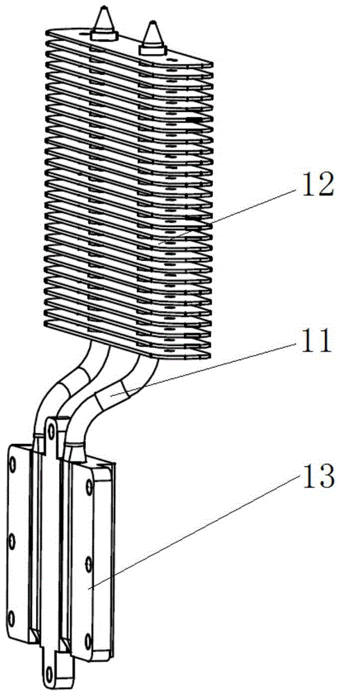
[0044] This embodiment provides a heat dissipation device for dissipating heat from the hot end of the semiconductor cooling fin. Specifically, the heat dissipation device includes a heat pipe and a radiator. Among them, the heat pipe has an evaporation section (such as figure 2 Evaporation section 211, evaporation section 212) and condensation section in. Wherein, there are at least two evaporating sections, and a condensing section is arranged between any two adjacent evaporating sections. The radiator is arranged on the condensing section of the heat pipe, and is used to radiate heat to the gaseous working medium in the condensing section to liquefy it.

[0045] Wherein, there are three heat pipes, and the evaporation section of the heat pipe is used to connect the hot end of the semiconductor cooling sheet (that is, different evaporation sections are connected with different semiconductor cooling sheet hot ends, or different evaporation sections are connected with differe...

Embodiment 2

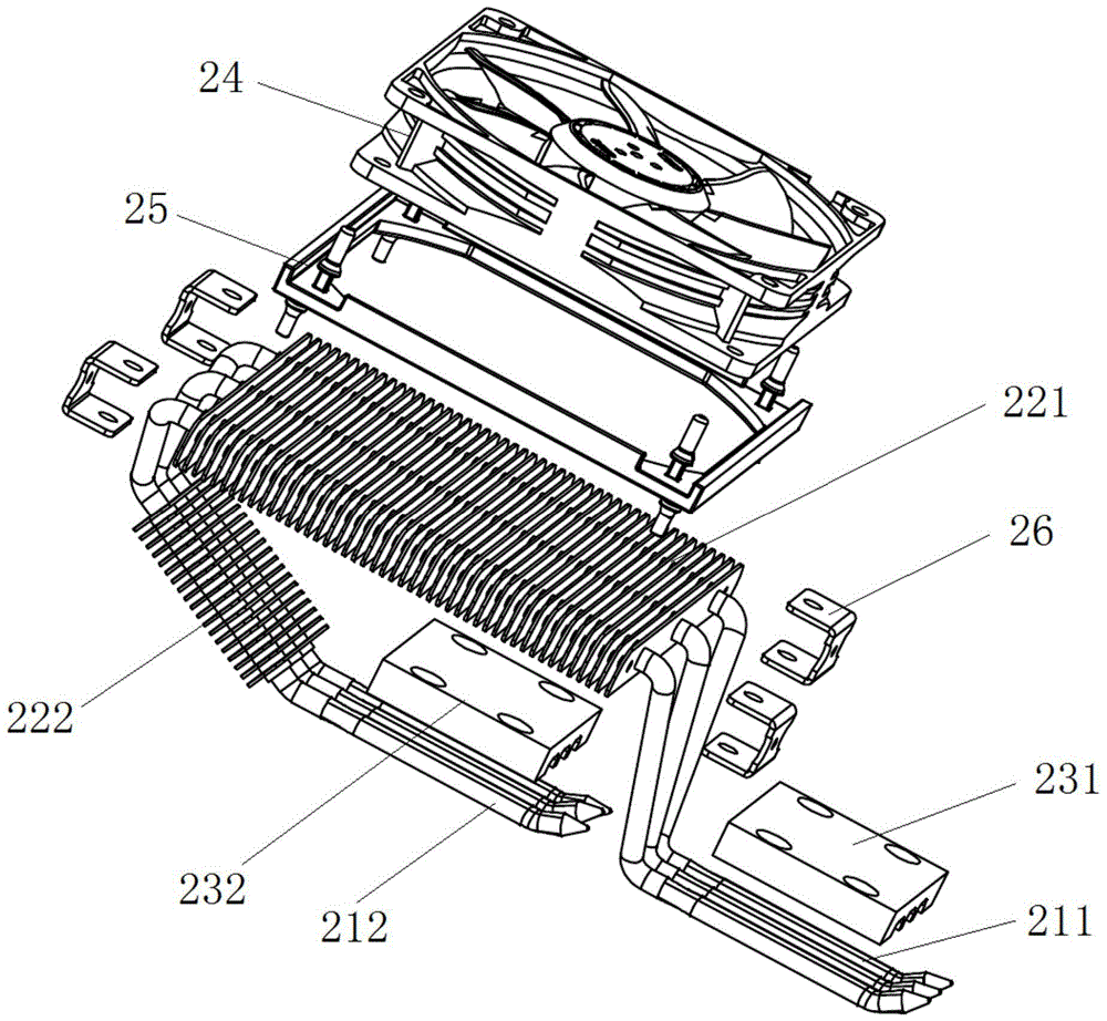
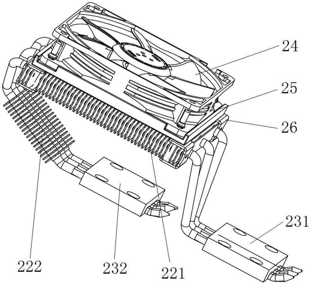
[0049] Such as figure 2 , image 3 and Figure 4 As shown, this embodiment provides a heat dissipation device for dissipating heat from the hot end of the semiconductor cooling fin. Compared with the previous embodiment, there are two evaporation sections on the heat pipe in this embodiment, one of which is the first The evaporation section 211, and the other is the second evaporation section 212. The first evaporating section 211 is located at one end of the heat pipe, the second evaporating section 212 is located at the other end of the heat pipe, and the condensing section is located between the first evaporating section 211 and the second evaporating section 212 . The radiator is set on the condensation section of the heat pipe (see figure 2 The cooling fin assembly 221, the cooling fin assembly 222 and the fan 24).

[0050] In this embodiment, the first evaporating section 211 and the second evaporating section 212 of the heat pipe are used to connect the hot end of...

Embodiment 3

[0053] Such as figure 2 , image 3 and Figure 4 As shown, this embodiment provides a heat dissipation device. Compared with Embodiment 2, the condensation section of the heat pipe in this embodiment includes a first condensation section and a second condensation section; wherein, the first condensation section and the second condensation section are in the form of The first setting angle β, where 0°<β≦90°; the second condensation section is located between the first condensation section and the second evaporation section 212 .

[0054] In this embodiment, the heat dissipation efficiency of the heat sink is further improved by dividing the condensation section into a first condensation section and a second condensation section, so that the first condensation section and the second condensation section cooperate to condense the gaseous working medium inside the heat pipe. Specifically, the second condensation section mainly condenses the gaseous working medium evaporated in ...


PUM


Abstract

The invention discloses a heat radiation device and a refrigerator, and relates to the technical field of heat radiation. According to the main technical scheme, the heat radiation device comprises a heat pipe and a heat radiator. The heat pipe is provided with a condensation segment and at least two evaporation segments. The condensation segment is arranged between any two adjacent evaporation segments. The heat radiator comprises cooling fin assemblies arranged on the condensation segment. The evaporation segments of the heat pipe are used for being connected with the hot end of a semiconductor refrigeration plate so that liquid work media in the evaporation segments can absorb heat of the hot end of the semiconductor refrigeration plate and then be vaporized. The vaporized work media diffuse in the condensation segment, and the vaporized work media in the condensation segment are cooled by the heat radiator to be liquefied. The liquefied work media flow back into the evaporation segments. The heat radiation device is mainly used for providing a heat pipe heat radiation structure suitable for the hot end of the semiconductor refrigeration plate, the heat radiation stability of the heat radiation device is improved, and the performance of the semiconductor refrigerator is guaranteed.

Description

technical field [0001] The invention relates to the technical field of heat dissipation, in particular to a heat dissipation device and a refrigerator. Background technique [0002] The refrigeration principle of semiconductor refrigerators is completely different from that of ordinary refrigerators. It uses semiconductor refrigerating sheets to achieve cooling through heat dissipation and conduction technology of heat sinks and automatic variable pressure and variable flow control technology. Among them, factors such as semiconductor material, power supply, and heat dissipation at the hot end will affect the cooling effect of the semiconductor cooler. Among these factors, the influence of semiconductor hot-side heat dissipation is particularly obvious. [0003] In order to improve the heat dissipation efficiency of the hot end of the semiconductor, the heat dissipation structure of the hot end of the semiconductor cooling fin gradually uses an integral sintered heat pipe f...

Claims


Application Information

Patent Timeline
Patent Type & Authority Patents(China)
IPC IPC(8): F28D15/02F25B21/02
Inventor 范兴发
Owner GREE ELECTRIC APPLIANCES INC
Why Eureka
Try Eureka