Supercharge Your Innovation With Domain-Expert AI Agents!

Luminescence module detection apparatus and luminescence module detection method

A technology of light-emitting modules and detection devices, applied in the direction of testing optical performance, etc., can solve problems such as deviation of detection results and increase of detection complexity.

Inactive Publication Date: 2014-10-15
致茂电子(苏州)有限公司
View PDF7 Cites 1 Cited by
  • Summary
  • Abstract
  • Description
  • Claims
  • Application Information

AI Technical Summary

Problems solved by technology

If the position of one of the LED optoelectronic components is detected by the secondary detection method of the prior art, it may be interfered by the light source emitted by other LED optoelectronic components, resulting in serious deviations in the detection results
In addition, even for LED optoelectronic components of the same specification, the light sources emitted may have individual differences. If the light source emitted by LED optoelectronic components is used for detection, it will also be interfered by the deviation of different light sources, and must be corrected separately. while increasing the complexity of detection

Method used


Image

  • Luminescence module detection apparatus and luminescence module detection method
  • Luminescence module detection apparatus and luminescence module detection method
  • Luminescence module detection apparatus and luminescence module detection method

Examples


Embodiment Construction

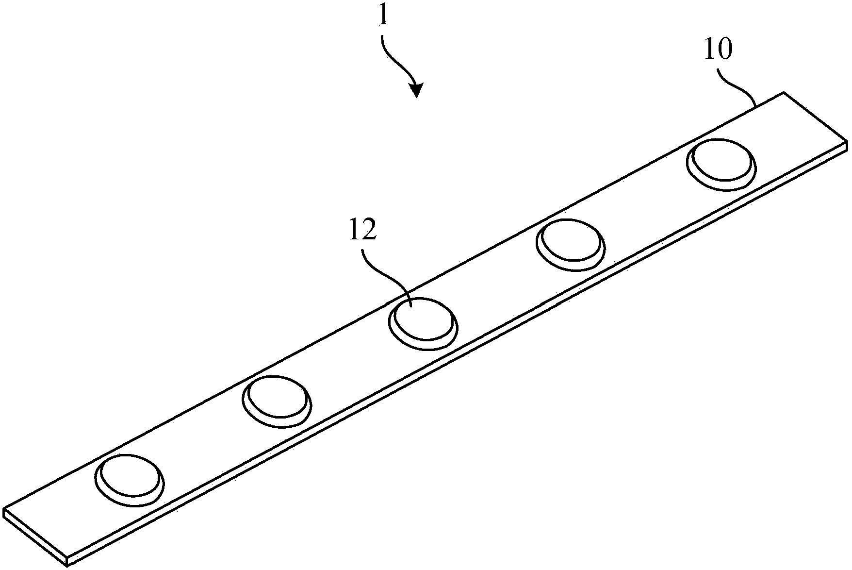
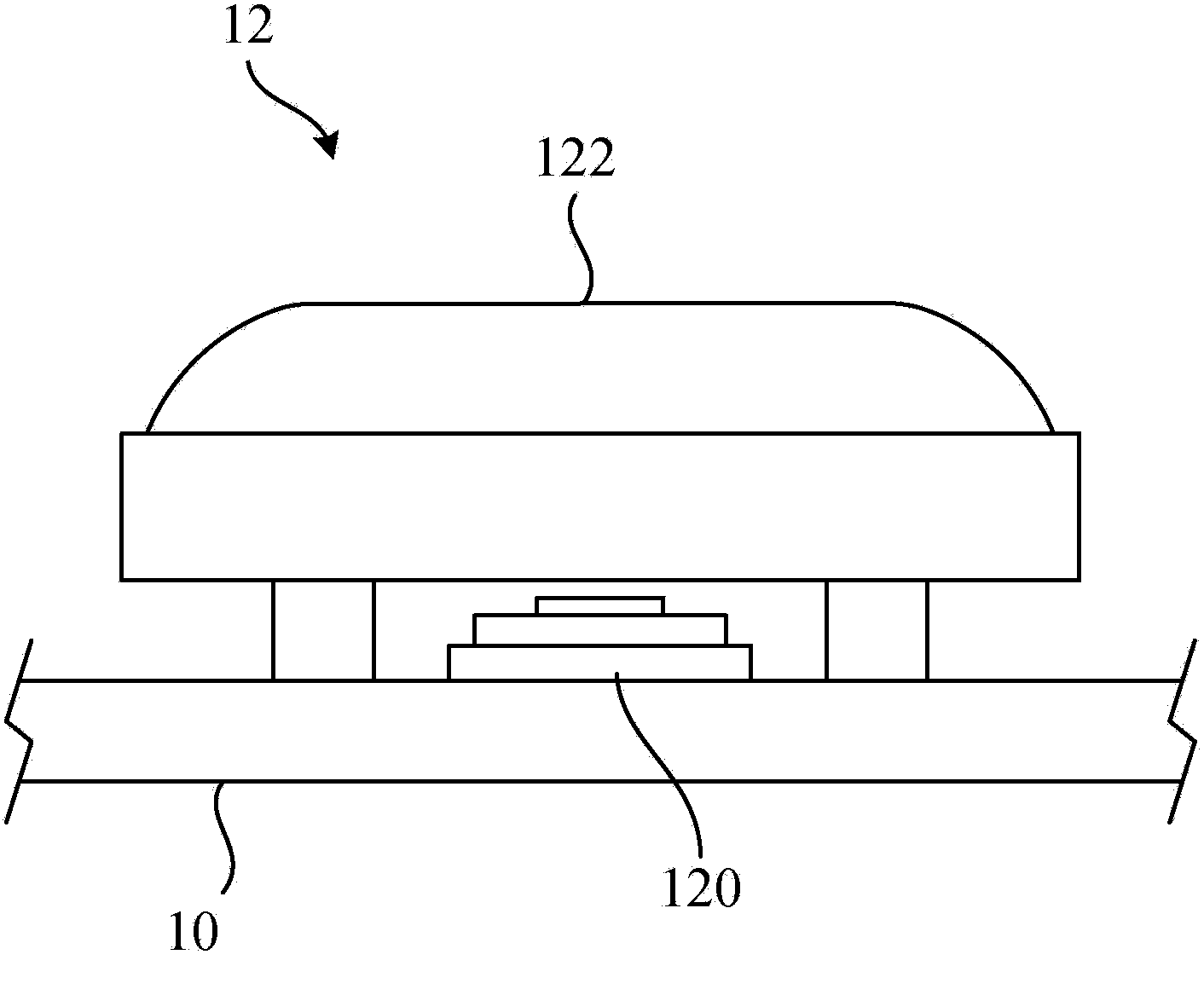
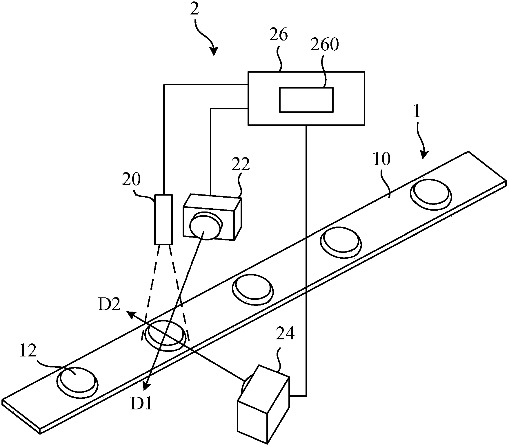
[0030] See figure 2 and image 3 , figure 2 Is a schematic diagram of the light-emitting module detection device 2 according to a specific embodiment of the present invention, image 3 Then figure 2 The light-emitting module detection device 2 of the above captures a detailed schematic diagram of the light-emitting element 120 and the lens 122. Such as figure 2 As shown, the light-emitting module detection device 2 can be used to detect the light-emitting module 1. In this specific embodiment, the light-emitting module 1 can refer to Figure 1A and Figure 1B Shown. The light-emitting module detection device 2 can be used to detect whether the light-emitting element 120 of the light-emitting module 1 is located at the center of its corresponding lens 122. The structure, function and relative relationship of each unit of the light-emitting module detection device 2 will be detailed below.

[0031] In this specific embodiment, the light-emitting module detection device 2 includes...


PUM


Abstract

The invention discloses a luminescence module detection apparatus and a luminescence module detection method. The luminescence module detection apparatus is used for detecting a luminescence module comprising a substrate, a luminescence element and a lens, wherein the luminescence element and the lens are arranged on the substrate. The luminescence module detection apparatus is also used for detecting whether the luminescence element is disposed at a center position of the lens. The luminescence module detection apparatus comprises a light source, a first camera unit and a second camera unit. The light source emits light to irradiate the lens and the luminescence element, and then the first camera unit and the second camera unit respectively acquire a first image and a second image from the lens and the luminescence element from a first side direction and a second side direction. An included angle not being zero exists between the first side direction and the second side direction. Through the first image, the second image and the included angle, the deviation between the luminescence element and the center position of the lens can be calculated.

Description

Technical field [0001] The present invention relates to a light-emitting module detection device and a light-emitting module detection method, and in particular, to a light-emitting module detection device and a light-emitting module detection method that can accurately calculate the deviation between a light-emitting element and a lens center position in a light-emitting module. Background technique [0002] Before high-power LED lighting components become lighting products, optical design is generally required to adjust the light source required by the LED. Primary optical design refers to adjusting the range and distribution of the light output angle, light intensity, luminous flux, light intensity distribution, and color temperature of the LED itself with a primary lens when the LED chip is packaged into an LED optoelectronic component. After an optical design of the LED optoelectronic component, its light-emitting angle is about 120 degrees. Since the LED optoelectronic com...

Claims


Application Information

Patent Timeline
IPC IPC(8): G01M11/02
Inventor 李明翰
Owner 致茂电子(苏州)有限公司
Features
  • R&D
  • Intellectual Property
  • Life Sciences
  • Materials
  • Tech Scout
  • Unparalleled Data Quality
  • Higher Quality Content
  • 60% Fewer Hallucinations
Learn More