Metal coordination compound, luminescence device and display apparatus
a technology of luminescence device and coordination compound, which is applied in the direction of indium organic compound, organic chemistry, other domestic articles, etc., can solve the problems of luminescence degradation and reduce the resultant luminescence efficiency especially at a higher current density
- Summary
- Abstract
- Description
- Claims
- Application Information
AI Technical Summary
Problems solved by technology
Method used
Image
Examples
example 7
[0111] A color organic EL display apparatus shown in FIG. 2 was prepared in the following manner.
[0112] An active matrix substrate had a planar structure basically similar to a structure described in U.S. Pat. No. 6,114,715.
[0113] Specifically, on a 1.1 mm-thick glass substrate, top state-type TFTs of polycrystalline silicon were formed in an ordinary manner and thereon, a flattening film was formed with contact holes for electrical connection with a pixel electrode (anode) at respective source regions, thus preparing an active matrix substrate with a TFT circuit.
[0114] On the active matrix substrate, a 700 nm-thick pixel electrode (anode) of ITO having a larger work function was formed in a prescribed pattern. On the ITO electrode, prescribed organic layers and a 100 nm-thick Al electrode (cathode) were successively formed by vacuum deposition with a hard mask, followed by patterning to form a matrix of color pixels (128.times.128 pixels).
[0115] The respective organic layers corres...
example 8
Synthesis of Example Compound No. 22
[0120] 10
[0121] In a 500 ml-three-necked flask, 12.6 g (85.2 mM) of 2,5-dichloropyridine, 15.2 g (85.4 mM) of benzothiophene-2-boronic acid, 75 ml of toluene, 37.5 ml of ethanol and 75 ml of 2M-sodium carbonate aqueous solution were placed and stirred at room temperature under nitrogen stream, and 3.06 g (2.64 mM) of tetrakis(triphenylphosphine)pall-adium (0) was added thereto, followed by refluxing under stirring for 8 hours under nitrogen stream. After the reaction, the reaction mixture was cooled on an ice bath to precipitate a crystal, which was then filtered out and washed with water. To the crystal, 100 ml of methanol was added and washed under stirring at room temperature, followed by filtration to recover the crystal. The crystal was purified by silica gel column chromatography (eluent: chloroform) and recrystallized from a mixture solvent of chloroform-methanol to obtain 11.8 g (Yield: 56.4%) of 5-chloro-2-(benzo[b]thienyl)pyridine (color...
example 9
Synthesis of Ex. Comp. No. 11
[0127] A metal coordination compound (Ex. Comp. No. 11) was synthesized through the following reaction schemes. Hereinafter, the synthesis yield is simply represented by "Y". 13
[0128] According to MALDI-TOF MS, the compound exhibited M.sup.+=919.0, thus being identified as the objective iridium compound.
[0129] When the compound was dissolved in toluene and subjected to measurement of phosphorescence spectrum at an excited light wavelength of 400 nm by using a fluorescence spectrometer, the compound exhibited a phosphorescence spectrum showing .lambda.max (maximum emission wavelength) of 612 nm, thus confirming clear red luminescence.
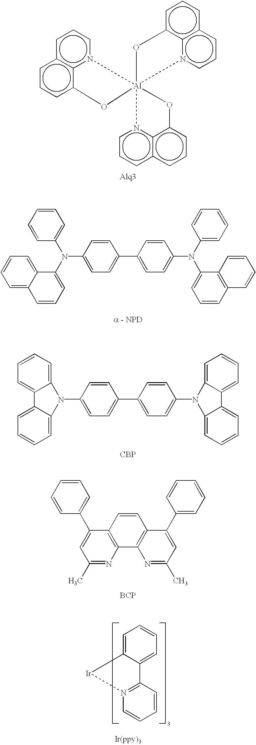
[0130] When a luminescence device having a layer structure shown below and using the above-synthesized metal coordination compound (Ex. Comp. No. 11) was prepared and subjected to measurement of phosphorescence spectrum in a similar manner, a clear red luminescence was confirmed similarly as in the case of the compound in tol...
PUM
| Property | Measurement | Unit |
|---|---|---|
| Electric potential / voltage | aaaaa | aaaaa |
| Luminance | aaaaa | aaaaa |
| Phosphorescence quantum yield | aaaaa | aaaaa |
Abstract
Description
Claims
Application Information
 - R&D
- Intellectual Property
- Life Sciences
- Materials
- Tech Scout
- Unparalleled Data Quality
- Higher Quality Content
- 60% Fewer Hallucinations
Browse by: Latest US Patents, China's latest patents, Technical Efficacy Thesaurus, Application Domain, Technology Topic, Popular Technical Reports.
© 2025 PatSnap. All rights reserved.Legal|Privacy policy|Modern Slavery Act Transparency Statement|Sitemap|About US| Contact US: help@patsnap.com


