Method for operating a brake system for motor vehicles, and brake system
A brake system and motor vehicle technology, applied in the direction of brake control system, brake safety system, brake transmission device, etc., can solve problems that are not described in detail
Active Publication Date: 2014-10-15
CONTINENTAL TEVES AG & CO OHG
7 Cites 16 Cited by
AI-Extracted Technical Summary
Problems solved by technology
In this application, it is not described in detail whether and possibly how the transition f...
Abstract
The invention relates to a method for operating a brake system for motor vehicles, comprising a master brake cylinder (12) that can be acuated by means of a brake pedal (1) and is separably (14a, 14b) connected to at least one hydraulically acutuatable wheel brake (6) by means of at least one brake circuit (I, II), a hydraulically operable pedal travel simulator (19) that is or can be connected to the master brake cylinder (12), an electrically controllable pressure provision apparatus (4) that is separably (27a, 27b) connected to the brake circuit (I, II), and an electronic open-loop and closed-loop control unit (7), wherein when the brake pedal (1) is actuated, a pressure (Ptarget) of the pressure provision apparatus (4) is applied to the brake circuit (I, II) in a first operating mode (ZA) and the pressure (PTHZ) of the master brake cylinder (12) is applied to the brake circuit (I, II) in a second operating mode (ZP), and wherein in the event of a transition from the second operating mode (ZP) to the first operating mode (ZA) while the brake pedal (1) is actuated, the actuation travel (SPedal) of the brake pedal (1) is adjusted by means of electronic open-loop or closed-loop control. The invention further relates to a brake system.
Application Domain
Brake control systemsFluid braking transmission +2
Technology Topic
Automotive engineeringElectricity +4
Image
Examples
- Experimental program(1)
Example Embodiment
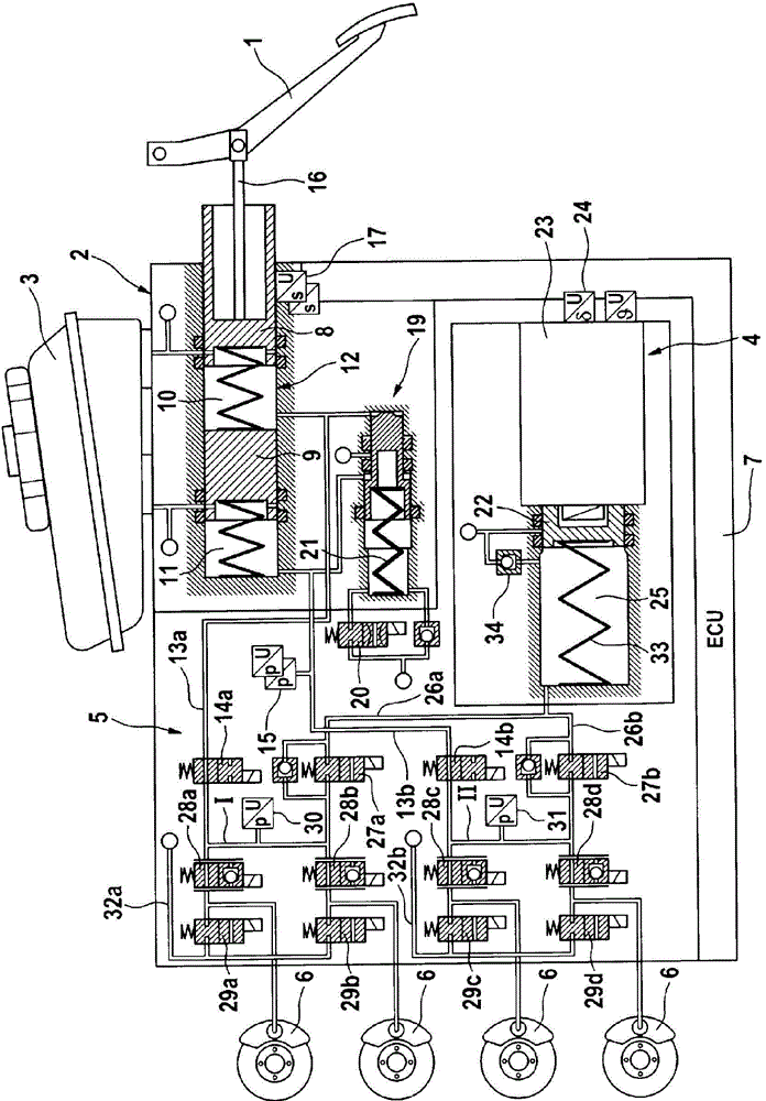
[0028] figure 1 An exemplary braking system is schematically shown in. The brake system includes an operating device that can be operated by the driver of the vehicle by means of the operation or brake pedal 1, a pressure medium storage container 3 allocated to the operating device 2, an electrically controllable pressure providing device 4, and an electrically controllable pressure A modulation device 5 and an electronic control and regulation unit 7 (ECU: electronic control unit). The output connection of the pressure modulation device is connected to a wheel brake 6 of a motor vehicle not shown. The electronic control and regulation unit is used For processing sensor signals and controlling electronically controllable components.
[0029] The operating device 2 includes a dual-circuit brake master cylinder or tandem master cylinder 12, which has two hydraulic pistons 8 arranged one after another in a (brake master cylinder) housing. 9. The piston defines the boundary of the hydraulic pressure chambers 10 and 11. The pressure chambers 10, 11 are connected to the pressure medium storage container 3 via radial holes formed in the pistons 8, 9, wherein the holes can be closed by the relative movement of the pistons 8, 9 in the housing. In addition, each pressure chamber 10, 11 is connected to the brake circuits I, II by means of hydraulic pipelines 13a, 13b. The brake circuits each have two wheel brake circuits, and the wheel brake circuits have hydraulic Operating wheel brake 6. A separating valve 14a, 14b is connected to the hydraulic pipeline 13a, 13b, and the separating valve is configured as an electrically operable, preferably normally open, two-position two-way reversing valve. The pressure sensor 15 which is connected to the pressure chamber 11 and is preferably configured redundantly detects the pressure P established in the pressure chamber 11 by the movement of the second piston 9 THZ The pressure corresponds to the pedal force generated by the driver. In addition, the pressure chambers 10, 11 contain return springs, not shown in detail, which pre-clamp the pistons 8, 9 against the operating direction. The piston rod 16 coupled with the brake pedal 1 cooperates with the first (master cylinder) piston 8, wherein a parameter S indicating the characteristic of the operating stroke of the brake pedal 1 Pedal For example, the operating stroke or angle of the brake pedal 1 itself or the operating stroke of the piston 8 coupled to the brake pedal is detected by a stroke sensor 17 which is preferably configured to be redundant.
[0030] In addition, the operating device 2 includes a pedal stroke simulator (also referred to as a pedal feel simulator device) 19, which interacts with the master cylinder 12 and presents the vehicle driver in a first operating mode (the so-called "Brown-by-wire" operating mode) delivers a pleasant pedal feel. The pedal stroke simulator 19 is hydraulically operated and connected with at least one pressure chamber 10, 11 of the master brake cylinder 12. The pedal stroke simulator 19 can be turned on and off by means of an electrically operable simulator release valve 20.
[0031] The pedal stroke simulator 19 is basically composed of two simulator chambers, one simulator spring chamber having a simulator spring 21, and simulator pistons (step pistons) separating the chambers from each other according to the example. Here, the simulator chambers are respectively connected to the pressure chambers 10 and 11 of the brake master cylinder 12, and the simulator spring chamber can be connected to the pressure medium storage container 3 with the simulator release valve 20 connected in the middle. The check valve connected in parallel with the simulator release valve 20 is connected to the simulator spring chamber and allows the pressure medium to flow regardless of the switching state of the simulator release valve 20 and regardless of the throttle effect of the hydraulic simulator outflow connection part. It flows largely into the simulator spring chamber without throttling. The simulator release valve 20 is configured as an electrically operable, preferably normally closed, two-position two-way reversing valve.
[0032] The electro-hydraulic pressure supply device 4 is configured as a hydraulic cylinder-piston device, the piston 22 of the cylinder-piston device can be operated by a schematically represented electric motor 23 with an unshown rotation-translation transmission device connected in between. The electric motor 23 and the rotation-translation transmission device form a linear actuator, in which a sensor 24 is present in order to detect a characteristic parameter with respect to the attitude/position of the piston 22 of the pressure providing device 4, which sensor is configured for The rotor position sensor 24 detects the rotor position of the electric motor 23. Other sensors, such as temperature sensors, provide the electronic control and regulation unit 7 with information about the state of the electric motor 23 or about the linear actuator. The piston 22 defines the boundary of a pressure chamber 25 which can be connected to the brake circuits I, II through hydraulic lines 26a, 26b each having electrically operable connection valves 27a, 27b. Here, a check valve closed to the pressure chamber 25 is connected in parallel with each of the closing valves 27a and 27b. Furthermore, the pressure chamber 25 is connected to the pressure medium storage container 3 via a non-return valve 34 which is closed toward the pressure medium storage container 3. The switching valves 27a, 27b are configured as electrically operable, preferably normally closed, two-position two-way reversing valves. The pressure chamber 25 is provided with a spring 33 which loads the piston 22 against the direction of pressure build-up.
[0033] In order to modulate the pressure on the wheel brakes 6, the hydraulic pressure modulating device 5 includes inlet valves 28a-28d and outlet valves 29a-29d for each wheel brake 6 according to an example. The input connection ends of the inlet valves 28a-28d or the brake circuits I, II can be supplied with the pressure of the brake master cylinder 12 (via the pipelines 13a, 13b with separating valves 14a, 14b) or the pressure of the pressure supply device 4 ( Via pipelines 26a, 26b with connection valves 27a, 27b). The output connection ends of the discharge valves 29a to 29d are connected to the pressure-free pressure medium storage container 3 via return lines 32a, 32b (so-called open system). As a supplement, it should be mentioned that all the circular symbols indicate the hydraulic pipeline leading to the pressure medium storage container 3. Advantageously, the inlet valves 28a-28d are configured as electrically operable normally open pressure regulating valves, and the outlet valves 29a-29d are configured as electrically operable normally closed two-position two-way reversing valves.
[0034] According to an example, each brake circuit I, II is provided with a pressure sensor 30, 31 for detecting the pressure existing on the input connection end of the associated inlet valve 28a, 28b, 28c, 28d. As an alternative, it is conceivable that a pressure sensor is provided on only one of the two brake circuits I, II or a pressure sensor is provided in the pipeline 26a, 26b between the pressure chamber 25 and the switching valve 27a, 27b. With the aid of the pressure sensor or these pressure sensors, the pressure P of the pressure providing device 4 can be determined ist (In the case where the separation valves 14a, 14b are closed).
[0035] In the first operating mode Z A (The so-called “brake-by-wire” operating mode with enhanced braking force), the brake circuits I and II are loaded with the pressure of the pressure supply device 4. For this reason, according to the example, the switching valves 27a, 27b are opened, whereby the pressure supply device 4 is hydraulically connected to the brake circuits I, II. The master brake cylinder 12 is separated from the brake circuits I, II or the wheel brakes 6 by means of closed separation valves 14a, 14b. The simulator release valve 20 is opened, whereby the pedal stroke simulator 19 is turned on or connected. Is operated on brake pedal 1 S Pedal In the case of, the pressure medium volume moves from the pressure chambers 10 and 11 of the master brake cylinder 12 to the simulator chamber of the pedal stroke simulator 19. The pressure providing device 4 is controlled by means of an electronic control and regulating unit 7 in order to provide a given pressure P for loading the brake circuits I and II Soll. The given pressure P of the pressure providing device 4 Soll The value of is, for example, in the electronic control and regulation unit 7 with the aid of a predetermined braking force enhancement function and the driver's braking expectation (S Pedal , P THZ ) To calculate.
[0036] According to the example, given pressure P Soll According to the following formula, the measured parameter P THZ And S Pedal to make sure:
[0037] P Soll =λ S *F S (S Pedal )+λ P *F P (P THZ )
[0038] Which means:
[0039] f s : With pedal stroke S Pedal The relevant brake pressure enhancement function,
[0040] f p : With pressure P THZ The relevant brake pressure enhancement function,
[0041] λ s : Used for pressure component f s The weighting factor or weighting function of
[0042] λ p : Used for pressure component f p The weighting factor or weighting function.
[0043] Given pressure P Soll Therefore, based on the pedal/piston stroke parameter S Pedal The pressure component f s And based on the pressure parameter P THZ The pressure component f p To obtain the weighted superposition. The weighting factors can take values between zero and one, for example. By increasing the function f at the preset brake pressure s , F p And the predetermined weighting factor λ s , Λ p On the one hand, corresponding pre-given or determination and parameter selection can realize the specific matching of the given pressure calculation with the current brake system and the expectations in the design of the brake system.
[0044] In the second operating mode Z P In the so-called standby operation mode, the brake circuits I and II are loaded with the pressure of the master cylinder 12. For this reason, the separation valves 14a, 14b are opened, and thereby, the master brake cylinder 12 is hydraulically connected to the brake circuits I, II. The pressure supply device 4 is separated from the brake circuits I, II or the wheel brakes 6 by means of closed switching valves 27a, 27b. The simulator release valve 20 is closed, and thus, the pedal stroke simulator 19 is turned off. Is operated on brake pedal 1 S Pedal In the case of, the volume of pressure medium moves from the pressure chambers 10 and 11 of the master brake cylinder 12 to the brake circuits I and II or the wheel brake 6.
[0045] in figure 2 According to the example for two operating modes Z A ,Z P The pressure P in the master cylinder 12 is shown schematically THZ With the operating stroke S Pedal The relationship between. Pressure P THZ Operation stroke S Pedal Curve, where the characteristic curve 40 represents the first operating mode Z A , The characteristic curve 41 represents the second operating mode Z P. The characteristic curve 40 or 41 indicates that in the corresponding operating mode Z A Or Z P Medium pressure P THZ And operating stroke S Pedal The nominal relationship between. According to the example, for two operating modes Z A ,Z P The corresponding characteristic curves 40 and 41 are stored in the electronic control and regulation unit 7.
[0046] In the first operating mode Z A The nominal pedal characteristic curve of the middle brake system, namely pedal force and pedal stroke S Pedal The relationship is basically determined by the simulator spring 21 of the pedal stroke simulator 19 (preferably a progressive compression spring, and other spring elements such as elastomer springs may be considered). Absorbed volume of pedal stroke simulator 19 and pedal stroke S Pedal Linear correlation. The pedal force and the pressure in the pedal stroke simulator 19 also have a linear relationship. Accordingly, a characteristic curve 40 is obtained, which is based on the pedal stroke S Pedal Describe the pressure in the pedal stroke simulator 19, which corresponds to the pressure P that can be measured by means of the pressure sensor 15 THZ. Indicates normal braking function ("wire control" operating mode, first operating mode Z A ) The nominal characteristic curve 40 is stored in the electronic control and regulation unit 7.
[0047] In the hydraulic standby mode (second operating mode Z P In ), the valves, especially the valves 14a, 14b, 20, 27a, 27b have no current, and the driver is directly hydraulically connected to the wheel brake 6 when the driver operates the brake pedal 1. Thus, according to the hydraulic design of the brake system and the vehicle-dependent volume reception of the wheel brake 6, other pedal characteristic curves are obtained, and the pressure P measured by the pressure sensor 15 THZ And pedal stroke S Pedal The relationship is described by the characteristic curve 41. Indicates the second operating mode Z P The nominal characteristic curve 41 is also stored in the electronic control and regulation unit 7. As from figure 2 As you can see, the two operating modes Z P And Z A The characteristic curve is significantly different.
[0048] image 3 A schematic flowchart explaining an exemplary method for operating a braking system is shown in.
[0049] If the vehicle is parked first or if the brake system is not supplied with electrical energy, the brake system is in a passive or off state 50 (the driver does not operate the brake pedal as a prerequisite). The braking system is usually activated, for example, by the driver by switching on the engine ignition or by opening the driver's door (optionally by means of corresponding environmental sensing devices, such as a keyless entry system). Initialization of the sensors of the brake system, the exemplary pressure sensors 15, 30, 31 and the position sensors 17, 24 is first performed in box 51, whereby the sensors provide measurement values after initialization. In box 52, the corresponding valves, the exemplary separation valves 14a, 14b, the simulator release valve 20 and the switch-on valves 27a, 27b, and the braking force enhancement function are activated, thereby, in the case of operating the brake pedal by the driver The "wire control" brake can be executed. The braking system is then in an active state ready for operation (first operating mode Z A , Box 65), in the active state, when the brake pedal 1 is operated, the separation valves 14a, 14b of the operating device 2 are closed, and the simulator release valve 20 and the switching valves 27a, 27b of the pressure supply device 4 are opened . The driver then does not directly connect hydraulically with the brake circuits I, II or the wheel brake 6, but operates the pedal stroke simulator 19, and the brake circuits I, II are loaded with the pressure P through the pressure supply device 4 Soll (According to a predetermined braking force enhancement function). The initialization path without driver operation (boxes 50, 51, 52, 65) is generally the normal case, that is, the valves 14a, 14b, 20, 27a, 27b are directly energized and the pressure providing device 4 is activated.
[0050] If the vehicle is parked (or if the brake system is not supplied with electrical energy) and if the driver operates the brake pedal 1, the brake system is in the second operating mode Z P (Standby operation mode). If the engine ignition is now switched on (or if the braking system is supplied with electrical energy again), the braking system will transition to the first operating mode Z according to the exemplary method described below A (Box 65), where the advantage of this method is that the transition is performed as comfortably as possible and without disturbing the driver.
[0051] A further distinction is made between the following two situations based on examples:
[0052] The first situation involves a situation in which the driver operates the brake pedal during the passive or off state, then the brake system is activated or initialized, and the driver continues to operate the brake pedal. This corresponds, for example, to a situation where the driver sits in a parked vehicle, operates the brake pedal, and then turns on the ignition. To explain the first situation, Figure 4 Pedal stroke S is shown in Pedal And belonging pressure P THZ An exemplary graph of.
[0053] That is, if the driver operates the brake pedal during the passive or off state (that is, the brake system is not initialized in advance), the brake system is in the second operating mode Z P (Standby operation mode) and Figure 4 The characteristic curve 41 works. Pedal stroke S Pedal And the brake circuit I, II corresponding to the pressure P of the master cylinder 12 due to the opened separation valves 14a, 14b THZ The corresponding system pressure of the wheel brake 6 appears at point 80 (S) according to the volume of the wheel brake 6 and the pedal force introduced by the driver. 1 , P 1 )on. Now if the brake system is activated by the driver via the engine ignition, first of all image 3 The initialization of the sensors of the brake system and the ECU 7 is performed in the block 53 of, thus, the pressure sensor 15 is used for the pressure P THZ Measured value and stroke/position sensor 17 for pedal stroke S Pedal The measured value is available for use. Then, in block 53, the simulator release valve 20 is opened, whereby the pedal stroke simulator 19 is turned on. The valves 14a, 14b, 27a, 27b are first kept without current. By turning on the pedal stroke simulator 19, the pedal stroke S Pedal The pedal force applied by the driver remains the same (i.e. Figure 4 Pressure in P 1 Keep the same) in the case of extending the receiving volume of the pedal stroke simulator 19, that is, the pedal stroke is Figure 4 From S 1 To S 2 extend.
[0054] Point 81(S 2 , P 1 ) Relative to the positions of the two nominal characteristic curves 40, 41 in box 56 by means of the current measured values (P THZ And S Pedal ) And the second operating mode Z stored in box 54 P The characteristic curve 41 and the box 55 stored for the second operating mode Z A The characteristic curve 40 is confirmed or compared to check. If identified in box 56: the point 81(S 2 , P 1 ) Is below the two nominal characteristic curves 40, 41, an active pedal correction is performed, for example by means of the pressure supply device 4 (branch 57 to box 58).
[0055] For this purpose, in the frame 58, the switching valves 27 a, 27 b are preferably opened first, whereby the pressure supply device 4 is hydraulically connected to the brake circuits I, II and thus also to the master brake cylinder 12. In addition, in box 58, the pressure supply device 4 is controlled such that the pressure medium volume moves from the pressure supply device 4 to the pressure chamber 10, of the brake master cylinder 12 through the opened connection valves 27a, 27b and separation valves 14a, 14b. In 11, therefore, the brake pedal 1 acts against the pedal force of the driver, that is, the constant pressure P 1 Reset. The reset of brake pedal 1 (pedal correction stroke) Figure 4 Is indicated by arrow 83. Brake pedal 1 is adjusted to the first operating mode Z A (“Brake-by-wire” operating mode) characteristic curve 40 at nominal point 82, whereby the adjusted pedal position corresponds to the (system) pressure P 1 The pedal stroke S obtained from the characteristic curve 40 3. The pedal position is checked by means of sensor 17.
[0056] After the pedal correction (box 58) is finished, in box 59, the master brake cylinder 12 is separated from the brake circuits I, II by closing the separation valves 14a, 14b. In box 60, the braking force is increased and then slowly increased until the braking system is then in the first operating mode Z in box 65 A ("Brake-by-wire" operating mode with enhanced braking force).
[0057] Through the above-mentioned processing method with brake pedal correction, the brake system is fast, comfortable and the driver transitions from the second operating mode to the first operating mode without confusion during the operation of the brake pedal. Especially through pedal correction, the brake system almost inconspicuously transitions from the state at point 81 to the "brake-by-wire" operating state for the driver. The "brake-by-wire" operating state corresponds to that of the first operating mode for driving. Point 82 on the characteristic curve 40 that the operator is accustomed to.
[0058] The second situation relates to the situation: the driver operates the brake pedal in the "brake-by-wire" operating mode, the brake system shifts to the standby operating mode (for example, due to a short-term power failure of the brake system), and then executes the brake system Restart or initialize, while the driver remains on the brake pedal. To explain the second case, Figure 5 Pedal stroke S is shown in Pedal And belonging pressure P THZ An exemplary graph of.
[0059] If the brake system is restarted during a “brake-by-wire” brake with increased braking force caused by operating the brake pedal (for example, caused by a short power failure), all valves of the brake system, especially The valves 14a, 14b, 20, 27a, 27b and the pressure supply device 4 have no power supply for a limited time, that is, no current. The braking system is therefore downgraded from the first operating mode with driver operation to the hydraulic standby mode, that is, the second operating mode Z in the case of driver operation. P in.
[0060] In the first operating mode, that is, before switching to the hydraulic standby mode, the master brake cylinder 12 is connected to the pedal stroke simulator 19 and Figure 5 The characteristic curve 40 works. Therefore, according to the pedal force applied by the driver, there is a pressure P on the master cylinder 12 or pedal stroke simulator 19 2 And there is pedal stroke S 4 (Point 84). There is a higher (system) pressure level in the brake circuits I and II due to the braking force enhancement function of the pressure providing device 4. After transitioning to the second operating mode Z P When the valves 20, 27a, 27b are closed and the separation valves 14a, 14b are opened, the brake pedal 1 changes from its pedal position S 4 When the pedal force remains the same, that is, the pressure P 2 In the same situation, the excess volume in the wheel brake 6 is pressed back for a long time until the corresponding pressure compensation is performed. This is Figure 5 Is indicated by arrow 86. This results in the pedal stroke S 5. At the same time, the piston 22 is reset to its hydraulic zero position by the spring 33. The pressure chamber 25 is filled here by a non-return valve/compensation suction valve 34.
[0061] If there is power supply then, first image 3 The initialization of the sensors of the brake system and the ECU 7 is performed in the block 53 of, whereby the measured value of the pressure sensor 15 and the measured value of the stroke/position sensor 17 are then available for use. In box 53, the simulator release valve 20 is also opened again. The valves 14a, 14b, 27a, 27b are first kept without current.
[0062] In box 56, the current measured values (P THZ And S Pedal ) And the characteristic curve 41 or 40 stored in the box 54 or 55 for confirmation or comparison to identify: the point 85 (S 5 , P 2 ) Is above the nominal characteristic curve 40. If this is the case, then an active pedal correction is performed, for example by means of the discharge valves 29a-d (branch 61 to box 62).
[0063] The pedal correction in the frame 62 is performed by opening the discharge valves 29a to 29d provided to the wheel brake 6 according to an example. The excess volume previously fed by the wheel brake 6 is discharged into the pressure medium storage tank 3 through the discharge valves 29a-d for a long time until the pedal stroke of the brake pedal 1 again corresponds to the corresponding value S of the nominal characteristic curve 40 4. In the box 62, the switching valves 27a, 27b are also opened, whereby the pressure supply device 4 is connected to the brake circuits I, II.
[0064] At the same time, the piston 22 of the pressure providing device 4 is adjusted to the piston position S Kolben , The piston position corresponds to the pressure P of the pressure providing device 4 equal to the pressure P in the master cylinder 12 THZ Pressure (P THZ =P 2 ). To this end, the pressure-stroke characteristic curve 42 of the pressure providing device 4 is stored in the control and regulation unit 7. Used to describe the piston position S of the pressure providing device 4 Kolben With pressure P DBE An exemplary characteristic curve 42 of the relationship between Image 6 Shown schematically in. Piston position S K1 Corresponding to pressure P DBE =P 2. Piston position S Kolben The inspection of the sensor 24 can be carried out.
[0065] If the pedal correction and the adjustment of the piston 22 are completed, the separation valves 14a, 14b are closed in block 59, and then the braking force is increased slowly in block 60 according to the driver's expectations, until the braking system is again in the first operating mode Z A ("Brake-by-wire" operating mode with enhanced braking force).
[0066] As a supplement to the above two cases (the first case and the second case), in a case where the driver's operation of the brake pedal 1 is small, pedal correction is not performed. For this, it is checked in box 56 whether the current pedal stroke S of the brake system Pedal Or the current operating point (S Pedal , P THZ ) Is at a predetermined threshold S g Below or, for example, through two thresholds S g And P g Within 44 of a certain predefined characteristic curve family (see Figure 4 with 5 ). If the pedal stroke S Pedal At threshold S g The following or operating point (S Pedal , P THZ ) Is within the range 44 of the characteristic curve family, then the actual pedal stroke deviates only very little or acceptably from the pedal stroke according to the nominal characteristic curve 40. So directly ( image 3 In the branch 63), that is, without pedal correction, in the box 64, the separating valves 14a, 14b are closed and the switching valves 27a, 27b are opened. Next, as has been described above for the first and second cases, the braking force enhancement is slowly increased by means of the pressure providing device 4 in the block 60. The brake system is then in the first operating mode Z A (With enhanced braking force "brake-by-wire" operating mode, normal braking function). After the brake pedal 1 is subsequently released, the brake system reappears on the nominal characteristic curve 40 by supplementing the missing (small) volume (through the connection of the pressure chambers 10, 11 to the pressure medium reservoir 3) .
PUM


Description & Claims & Application Information
We can also present the details of the Description, Claims and Application information to help users get a comprehensive understanding of the technical details of the patent, such as background art, summary of invention, brief description of drawings, description of embodiments, and other original content. On the other hand, users can also determine the specific scope of protection of the technology through the list of claims; as well as understand the changes in the life cycle of the technology with the presentation of the patent timeline. Login to view more.