Radiation Energy Collector And Lamellae And Lamella Assembly For The Same

A radiant energy collector technology, applied in the field of radiant energy collectors, can solve problems such as easy failure, complex structure, increased installation size or height, etc.

Inactive Publication Date: 2014-10-22
雷诺汉斯
View PDF3 Cites 8 Cited by
  • Summary
  • Abstract
  • Description
  • Claims
  • Application Information

AI Technical Summary

Problems solved by technology

In order to prevent overheating, it is necessary to adopt a cooling structure or take other measures, which are often complex and sometimes prone to failure
[0007] Another problem is that existing radiant energy collectors are not sufficiently integrated in the roof structure, and especially some structural features such as sealing means and / or thermal insulation means are partially redundant or double provided, which makes the structure complex and Increased installation size or height

Method used


Image

  • Radiation Energy Collector And Lamellae And Lamella Assembly For The Same
  • Radiation Energy Collector And Lamellae And Lamella Assembly For The Same
  • Radiation Energy Collector And Lamellae And Lamella Assembly For The Same

Examples


Embodiment Construction

[0041] Features in the following description are considered to be combinable with each other even if the combination is not explicitly stated, unless such a combination is contradictory or technically impossible. Often, the same reference number represents the same component in different drawings.

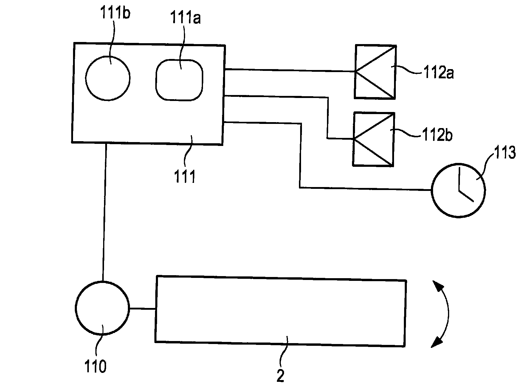
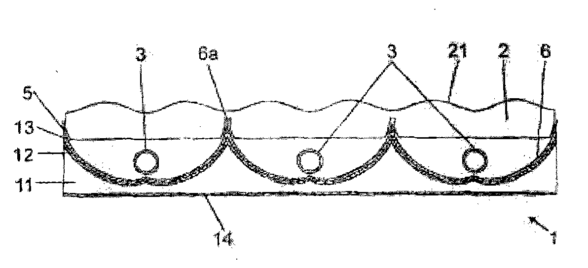
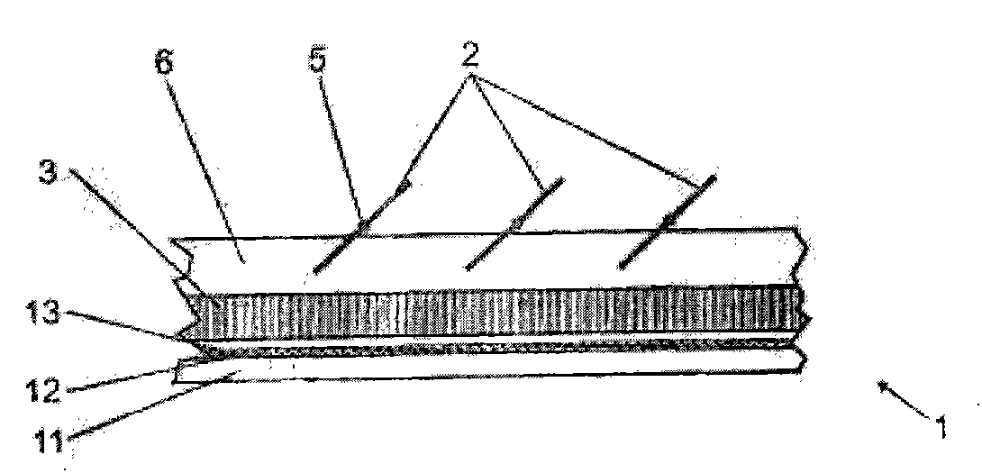
[0042] Figures 1(a-c) illustrate several features and embodiments of the present invention in combination with top, side and cross-sectional views. Figure 1a A cross-sectional view of a radiant energy collector is shown. In the case of the fluid guiding means (as shown schematically) this can be either a vacuum tubular collector or a flat plate collector.

[0043] In the illustrated embodiment, the flow guiding device 3 is designed as a vacuum line or the like. Several can be arranged in physical parallel, as shown in the figure. They can be in parallel or serial fluid communication with each other. The entire radiant energy collector 1 can be configured as a panel. The panel...


PUM


Abstract

A radiant energy collector (1) for collecting radiant energy of a source, in particular the energy of the sun, is provided. The energy collector has a first support piece (4) and a fluid guide device (2) capable of absorbing radiation and installed on the support piece (4). One or more blades (2) fixed on the support piece (4) directly or indirectly and a connection device (5) fixed on the support piece (4) directly or indirectly are arranged in front of the fluid guide device (2) capable of absorbing radiation on a radiation path. The panel-type radiation energy collector (1) is used for collecting energy radiated by a radiation source and the sun and is provided with the fluid guide device (3) and an insulation layer (11) connected with the fluid guide device (3) connected with the fluid guide device (3) directly or indirectly. From the perspective of radiation source, the insulation layer is disposed below the fluid guide device (3) or below a reflector (6) of the fluid guide device and is designed as a thermal insulation device of a building roof area or a wall area for the radiation energy collector (1).

Description

technical field [0001] The present invention relates to radiant energy collectors, such as flat plate collector panels or evacuated tubular collector panels. Background technique [0002] Such panels can be designed as flat plate collectors or evacuated tubular collectors. Flat-plate collectors are characterized by their flat construction and the horizontal arrangement of the absorbers. Usually, a glass plate is installed as a top cover above the absorber surface with air gaps. Underneath the absorber surface is in most cases thermal insulation, preferably made of mineral wool. The absorbers are usually provided with special selective coatings which absorb the highest possible proportion of solar energy in the form of heat. [0003] The thermal energy is discharged to the heat store with the help of a liquid via a pipe system fixedly connected to the surface of the absorber. However, such flat-plate collectors have the disadvantage that their effectiveness rapidly decrea...

Claims


Application Information

Patent Timeline
Patent Type & Authority Applications(China)
IPC IPC(8): F24J2/46F24S10/70F24S23/70
CPCF24J2002/108F24J2002/1095F24J2/1047F24S10/45F24S10/742F24S23/80F24S40/52F24S2023/872F24S2023/878Y02B10/20Y02E10/44
Inventor 雷诺·汉斯
Owner 雷诺汉斯
Why Eureka
Try Eureka