
Chopper based infrared imagery heterogeneity correction method

A non-uniformity correction, infrared image technology, applied in image enhancement, image data processing, instruments, etc., can solve the problem of impossible installation of photoelectric angle measurement and positioning code disc, small size of infrared detector, automatic identification of high temperature images, background image Automatic discrimination, low temperature image automatic discrimination and other issues

Active Publication Date: 2014-10-22
TIANJIN JINHANG COMP TECH RES INST
View PDF5 Cites 6 Cited by
  • Summary
  • Abstract
  • Description
  • Claims
  • Application Information

AI Technical Summary

Problems solved by technology

This method innovates on the basis of real-time correction based on deformable lens, and designs and uses choppers with different occlusion effects to replace the correction technology of the original deformable mirror; at the same time, it proposes a solution of chopping correction technology to solve the problem of infrared image integral signal and The problem of synchronous relationship between chopping stepping and rotation cycle; because the infrared detector is very small, it is impossible to install the photoelectric angle measurement and positioning code disc, so it is necessary to solve the automatic discrimination of high temperature images, automatic discrimination of background images, and automatic discrimination of low temperature images. Discrimination, semi-occlusion automatic discrimination, etc., so as to realize image non-uniformity correction based on chopping

Method used

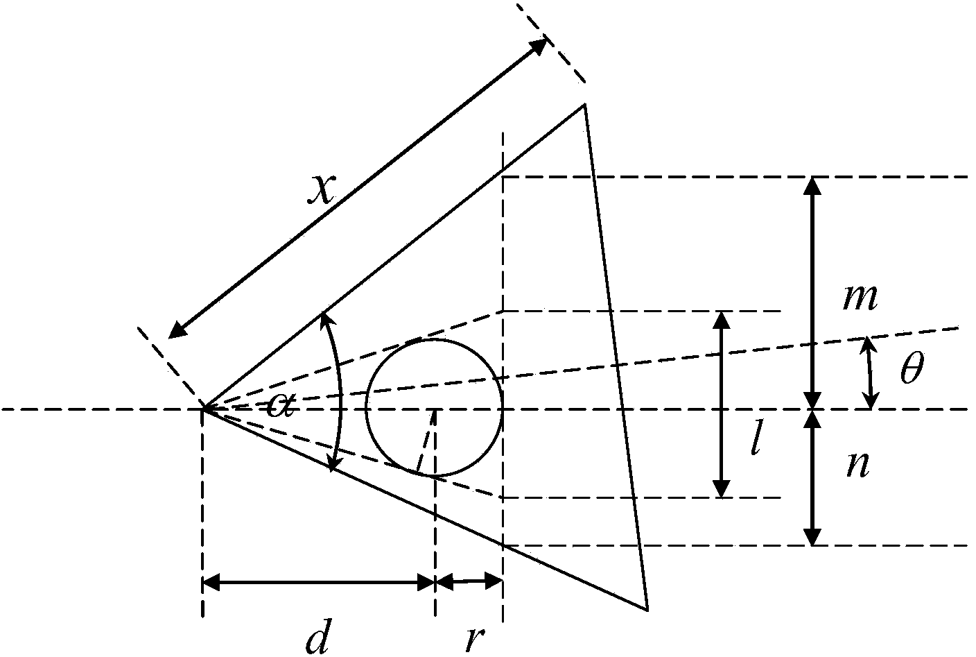
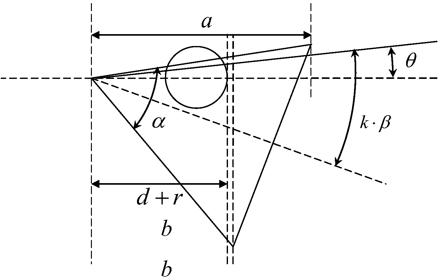

Image

  • Chopper based infrared imagery heterogeneity correction method
  • Chopper based infrared imagery heterogeneity correction method
  • Chopper based infrared imagery heterogeneity correction method

Examples


Embodiment Construction

[0031] Examples of the present invention will be described below in conjunction with the accompanying drawings. The embodiments described here are only used to illustrate and explain the present invention, and are not intended to limit the present invention.

[0032] A kind of chopper-based infrared image non-uniformity correction method of the present invention, specific implementation steps are as follows:

[0033] Step 1. Design the structural scheme of the chopper shielding sheet with dual temperature characteristics:

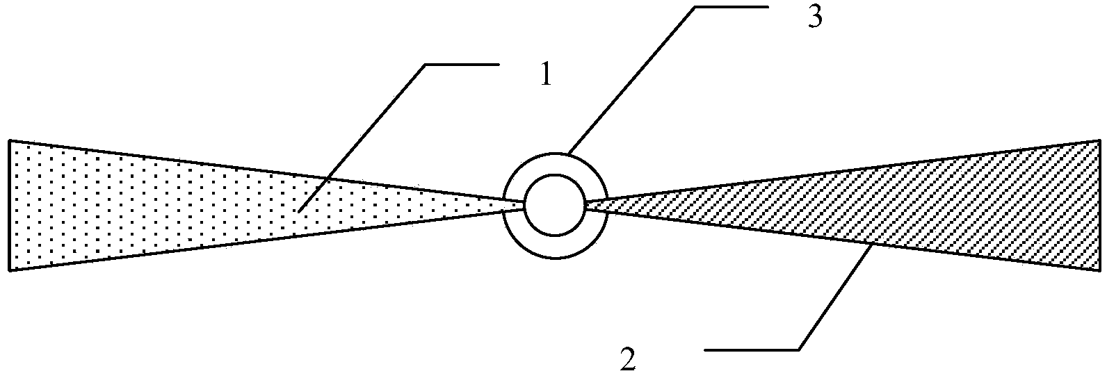
[0034] Choppers with dual temperature characteristics (see figure 1 ) mainly includes a connector 3, a gray body shielding sheet 2, and a diffuse reflection shielding sheet 1; wherein the connector 3 is connected with the gray body shielding sheet 2 and the diffuse reflection shielding sheet 1, and drives the gray body shielding sheet 2 and the diffuse reflection shielding sheet 1 to rotate , the gray body shading sheet 2 is a fan-shaped structure, the sur...


PUM


Abstract

The invention discloses a chopper based infrared imagery heterogeneity correction method. According to the chopper based infrared imagery heterogeneity correction method, innovation is made on the basis of distortion lens real-time correction, and a chopper with different shielding effects is designed and applied to replace correction technology of an original distortion lens; meanwhile, a solution method of chopping correction technology is provided to solve the problem of the synchrony relationship between an infrared imagery integrated signal and chopping stepping and rotation periods; since an infrared detector is small in size and a photoelectric angle measurement alignment code disc cannot be installed, automatic identification of high-temperature images, background images, low-temperature images, and half-shielding needs achieving, so that chopping based imagery heterogeneity correction is achieved.

Description

technical field [0001] The invention belongs to the technical field of infrared focal plane detectors, and in particular relates to a chopper-based infrared image non-uniformity correction method. Background technique [0002] Infrared Focal Plane Array IRFPA (Infrared Focal Plane Array) has fixed pattern noise FPN (Fixed Pattern Noise) in the detector array due to the non-uniformity and instability of the detector itself or the response between detector elements. One of the main factors limiting the improvement of imaging quality. Therefore, the non-uniformity correction NUC (Non_Uniformity Correction) problem of IRFPA has become a hot research technology at home and abroad. [0003] Usually, thermal imaging cameras are mostly calibrated by a radiation reference source, and the correction coefficient is read out when the detector is working normally, and non-uniformity correction is performed on the input image in real time. However, since the FPN changes slowly with time...

Claims


Application Information

Patent Timeline
IPC IPC(8): G01J5/00G01J5/08G06T5/00
Inventor 杨硕周津杨阳
Owner TIANJIN JINHANG COMP TECH RES INST
Learn More