

seat switch device
A switch device, contact switch technology, applied in electrical switches, electrical components, circuits, etc., can solve the problems of increased detection error, damage to deformation ease, and increased error of detection pressure, so as to improve responsiveness and accuracy. , the overall compact effect of the device
- Summary
- Abstract
- Description
- Claims
- Application Information
AI Technical Summary
Problems solved by technology
Method used
Image

Examples
Embodiment Construction
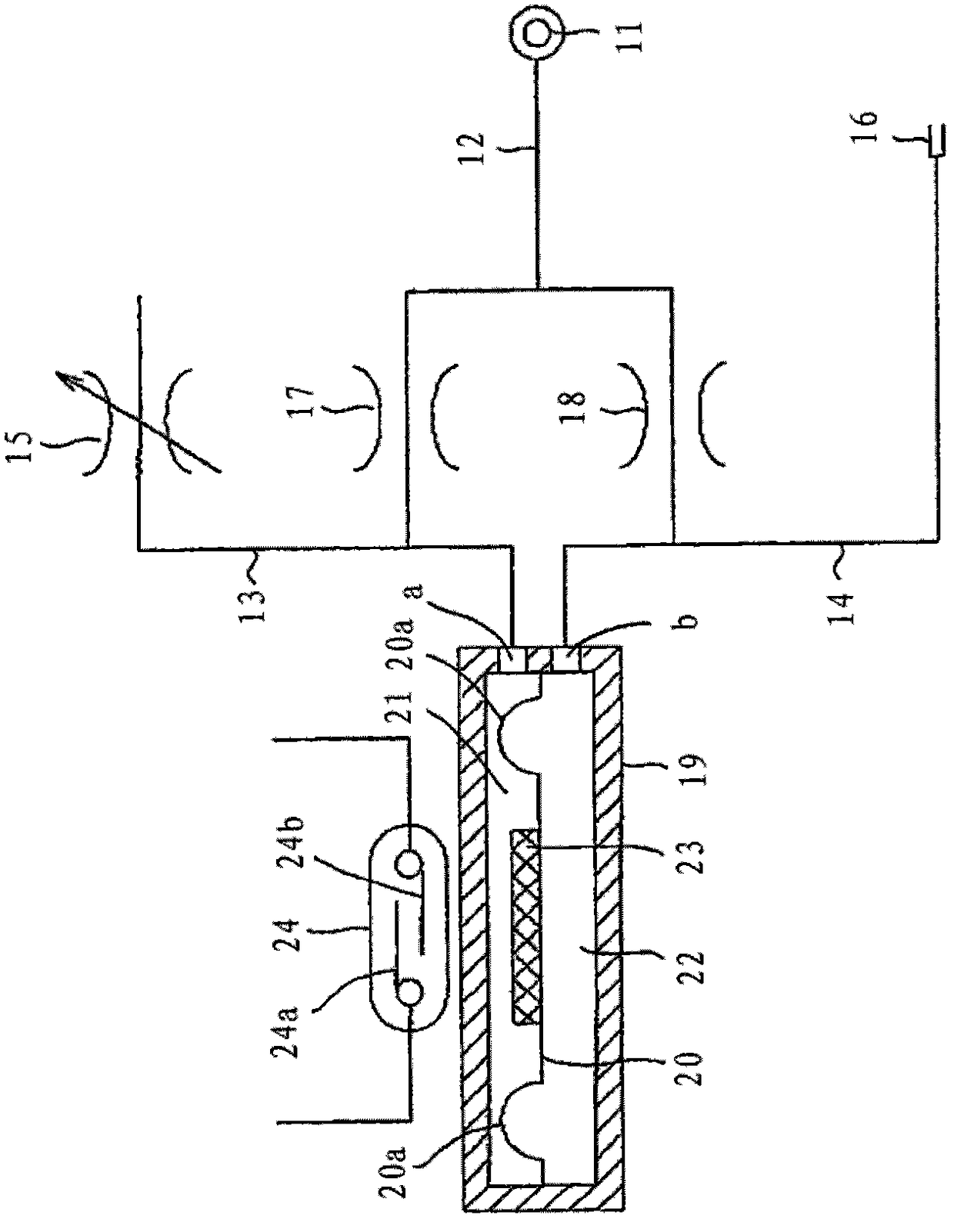
[0048] exist figure 1 In the illustrated first embodiment, the set pressure side passage 13 and the detection side passage 14 are connected in parallel to the pressure source 11 including a compressor or the like via the supply passage 12 . Furthermore, a set pressure regulator 15 comprising a variable orifice is connected to the set pressure side passage 13 , and a detection nozzle 16 is provided in the detection side passage 14 .
[0049] In addition, reference numeral 17 in the figure is an orifice provided in the set pressure side passage 13 , and 18 is an orifice provided in the detection side passage 14 .
[0050]On the other hand, a diaphragm 20 , which is a membrane member of the present invention, is installed in a case 19 that introduces the pressures of the set pressure side passage 13 and the detection side passage 14 , and the inside of the case 19 is divided into pressure chambers 21 and 22 . In addition, the mark 20a in a drawing is the fold part provided in t...
PUM
 Abstract
Description
Claims
Application Information