Low Voltage Darlington Amplifier

An amplifier and low-voltage technology, applied in the field of low-voltage Darlington amplifiers, can solve the problems of deteriorating noise figure, deteriorating input voltage standing wave coefficient, and high terminal voltage of Darlington amplifier devices, and achieving the effect of avoiding noise figure

Active Publication Date: 2016-10-19
NO 24 RES INST OF CETC
View PDF5 Cites 0 Cited by
  • Summary
  • Abstract
  • Description
  • Claims
  • Application Information

AI Technical Summary

Problems solved by technology

Compared with the traditional Darlington amplifier, this solution only eliminates the voltage drop on the bias resistor, but the device terminal voltage of the device Darlington amplifier itself does not change, so it cannot solve the problem of the high device terminal voltage of the Darlington amplifier. The problem, and because the self-bias part is connected to the circuit signal input terminal, it will cause a series of problems such as deteriorating the noise figure and deteriorating the standing wave coefficient of the input voltage.

Method used


Image

  • Low Voltage Darlington Amplifier
  • Low Voltage Darlington Amplifier
  • Low Voltage Darlington Amplifier

Examples


Embodiment Construction

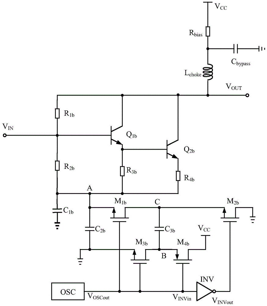
[0020] The circuit diagram of the low-voltage Darlington amplifier embodied by the present invention is as figure 2 shown. It includes a basic Darlington amplifying unit, an AC-DC separation unit and a power supply voltage polarity conversion unit. Its specific structure, connection relationship, and functional relationship are the same as the content of the invention in this specification, and will not be repeated here.

[0021] The operating principle of the circuit of the present invention is as follows:

[0022] RF signal through V IN After the port enters the Darlington amplifier, through the transistor Q 1b and transistor Q 2b After the signal is amplified by the composite Darlington tube composed of V OUT port output. Resistance R 1b and resistor R 2b Determine the transistor Q 1b Base operating point, and play an important role in the gain, bandwidth, input impedance and noise of the Darlington amplifier, the resistance R 4b is the transistor Q 1b The emitt...


PUM


Abstract

The invention discloses a low-voltage Darlington amplifier. It includes a basic Darlington amplifying unit, an AC-DC separation unit and a power supply voltage polarity conversion unit. The circuit of the present invention separates the AC and DC grounds of the Darlington amplifier unit, and clamps the AC ground to the ground; the circuit of the present invention clamps the DC reference ground of the Darlington amplifier to a negative reference level, thereby improving the power supply Potential difference between voltage and DC reference ground. The power supply voltage of the traditional Darlington amplifier is generally higher than 5-7V, and the power supply voltage of the low-voltage Darlington amplifier of the present invention can be as low as 3-4V. The invention is widely used in various Darlington structure circuits in microwave monolithic ICs.

Description

technical field [0001] The invention relates to a Darlington amplifier, in particular to a low-voltage Darlington amplifier, which is directly applied to the field of various Darlington circuits in microwave monolithic ICs. Background technique [0002] The amplifier is a key unit in the RF signal processing system, and its performance directly determines the performance of the RF signal processing system. Darlington amplifiers have been widely used because of their wide operating frequency band, high linearity, and easy cascading. [0003] When the Darlington amplifier is working, it needs an external bias current, which is generally realized by a voltage source and an external bias resistor. The larger the voltage drop across the bias resistor, the more stable the Darlington amplifier's bias current is over temperature and voltage variations. In order to obtain a stable bias, a voltage drop of at least 1-2V is generally required across the bias resistor. In order to obt...

Claims


Application Information

Patent Timeline
Patent Type & Authority Patents(China)
IPC IPC(8): H03F3/345
Inventor 刘成鹏王国强何峥嵘邹伟蒲颜
Owner NO 24 RES INST OF CETC
Why Eureka
Try Eureka