
Ink jet recording apparatus and method of controlling the same

a technology of recording apparatus and ink jet, which is applied in the direction of printing mechanism, power drive mechanism, printing, etc., can solve the problems of complex changes in the physical properties of ink, and inability to stably record images of high image quality, etc., to achieve stably recording images and high image quality for a long time

Inactive Publication Date: 2005-09-15
FUJIFILM CORP +1
View PDF5 Cites 9 Cited by
  • Summary
  • Abstract
  • Description
  • Claims
  • Application Information

AI Technical Summary

Benefits of technology

[0013] In light of the foregoing, the present invention has been made in order to solve the above-mentioned problems, and it is, therefore, an object of the present invention to provide an ink jet recording apparatus which is capable of stably ejecting ink droplets, thereby stably forming an image of high image quality.
[0024] Preferably, when the detected value is smaller than the desired value, the updating is carried out by at least one of further increasing the potential difference, shortening the distance, and increasing the ink temperature, while when the detected value is larger than the desired value, the updating is carried out by at least one of decreasing the potential difference, increasing the distance, and decreasing the ink.
[0031] According to the present invention, since the spontaneous ejection property is detected and the ejecting conditions are adjusted in accordance with the detected spontaneous ejection property, the detected spontaneous ejection property can be fixed irrespective of the factors for changing the spontaneous ejection property. Thus, it becomes possible to stably record an image of high image quality for a long time.

Problems solved by technology

As a result, there is encountered a problem that an image of high image quality cannot be stably recorded since a change occurs in the recorded image.
However, in the ink jet recording apparatus, the gap defined between the ink jet head and the recording medium, the resistance of the recording medium, and the physical properties of the ink complexly change.
Thus, there is encountered a problem that since the ejection state of the ink droplets can not be fixed, an image of high image quality can not be stably formed.

Method used


Image

  • Ink jet recording apparatus and method of controlling the same
  • Ink jet recording apparatus and method of controlling the same
  • Ink jet recording apparatus and method of controlling the same

Examples


Embodiment Construction

[0045] An ink jet recording apparatus and a method of controlling the same according to the present invention will hereinafter be described in detail based on preferred embodiments of the present invention shown in the accompanying drawings.

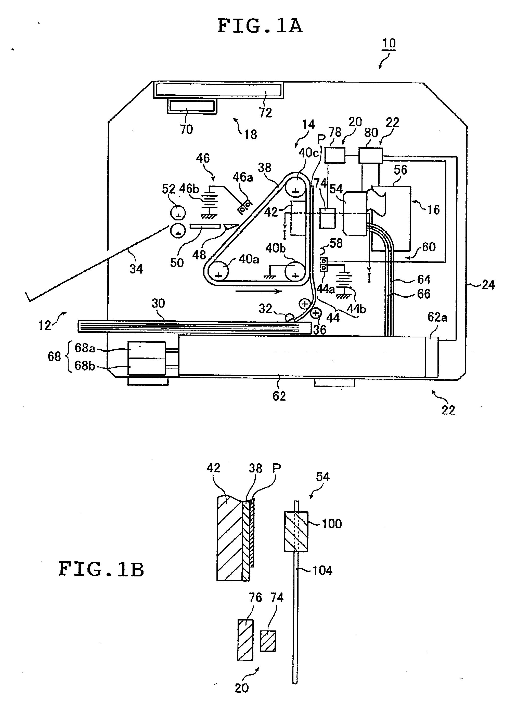
[0046]FIG. 1A is a schematic view showing an overall construction of an ink jet recording apparatus according to an embodiment of the present invention. FIG. 1B is a cross sectional view taken along the line I-I of FIG. 1A.

[0047] An ink jet recording apparatus 10 shown in FIG. 1A is an electrostatic type ink jet recording apparatus with which ejection of ink containing charged colorant particles is controlled by utilizing an electrostatic force to record a monochrome image on a recording medium P. The ink jet recording apparatus 10 includes means 12 for holding the recording medium P, conveyance means 14, recording means 16, solvent collection means 18, ejection property detecting means 20, ejecting condition control means 22 and a casing 24.

[...


PUM


Abstract

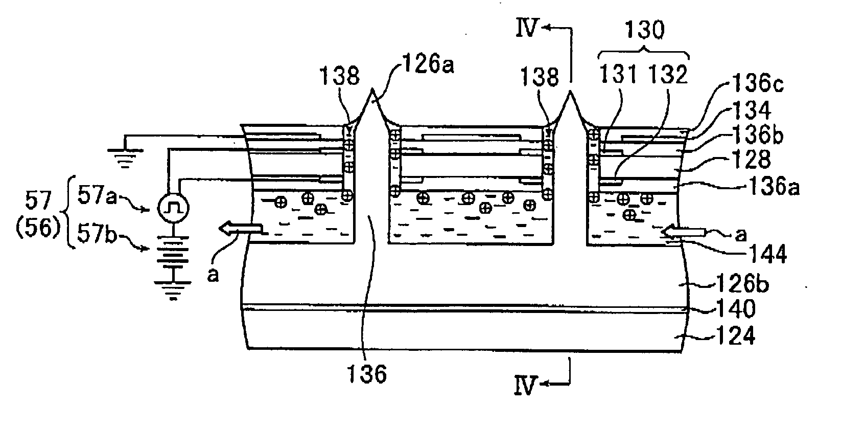
An ink jet recording apparatus ejects ink droplets toward a recording medium by causing an electrostatic force to act on ink containing charged colorant particles. The ink jet recording apparatus includes ink ejecting device for ejecting the ink droplets by causing a predetermined electrostatic force to act on the ink, ejection property detecting device for detecting a spontaneous ejection property of the ink droplets, and ejecting condition control device for controlling ejecting conditions for the ink droplets according to the spontaneous ejection property detected by the ejection property detecting device.

Description

[0001] This application claims priority on Japanese patent application No. 2004-68656, the entire contents of which are hereby incorporated by reference. In addition, the entire contents of literatures cited in this specification are incorporated by reference. BACKGROUND OF THE INVENTION [0002] The present invention relates to an ink jet recording apparatus for ejecting ink droplets toward a recording medium by causing an electrostatic force to act on ink containing charged colorant particles, and a method of controlling the same. [0003] As for a recording method with which ink droplets each containing colorant particles are ejected to record an image on a recording medium, for example, there is known an electrostatic ink jet recording system in which ejection of ink droplets is controlled by utilizing an electrostatic force through application of a predetermined voltage (drive voltage) corresponding to image data to an ejection electrode of an ink jet head, thereby recording an ima...

Claims


Application Information

Patent Timeline
IPC IPC(8): B41J2/06B41J2/01B41J2/41
CPCB41J2/06
Inventor NAKAZAWA, YUSUKE
Owner FUJIFILM CORP
Learn More