
Liquid recycling bin

A liquid recovery and box technology, which is applied in cleaning equipment, household appliances, applications, etc., can solve the problems of limiting the use range of hard surface liquid recovery devices, and achieve the effect of improving work efficiency

Inactive Publication Date: 2014-10-29
宋振宇 +1
View PDF0 Cites 0 Cited by
  • Summary
  • Abstract
  • Description
  • Claims
  • Application Information

AI Technical Summary

Problems solved by technology

[0002] The structure of the water storage and recovery tank of the existing hard surface liquid recovery device is a whole structure, and the collected water is collected into the water storage and recovery tank through the water inlet pipe. Since the water inlet pipe and the vent hole are straight pipes, when the use position changes , for example, when inverted, the collected liquid will flow back through the water inlet pipe and the vent hole, which greatly limits the scope of use of the existing hard surface liquid recovery device

Method used


Image

  • Liquid recycling bin
  • Liquid recycling bin
  • Liquid recycling bin

Examples


Embodiment Construction

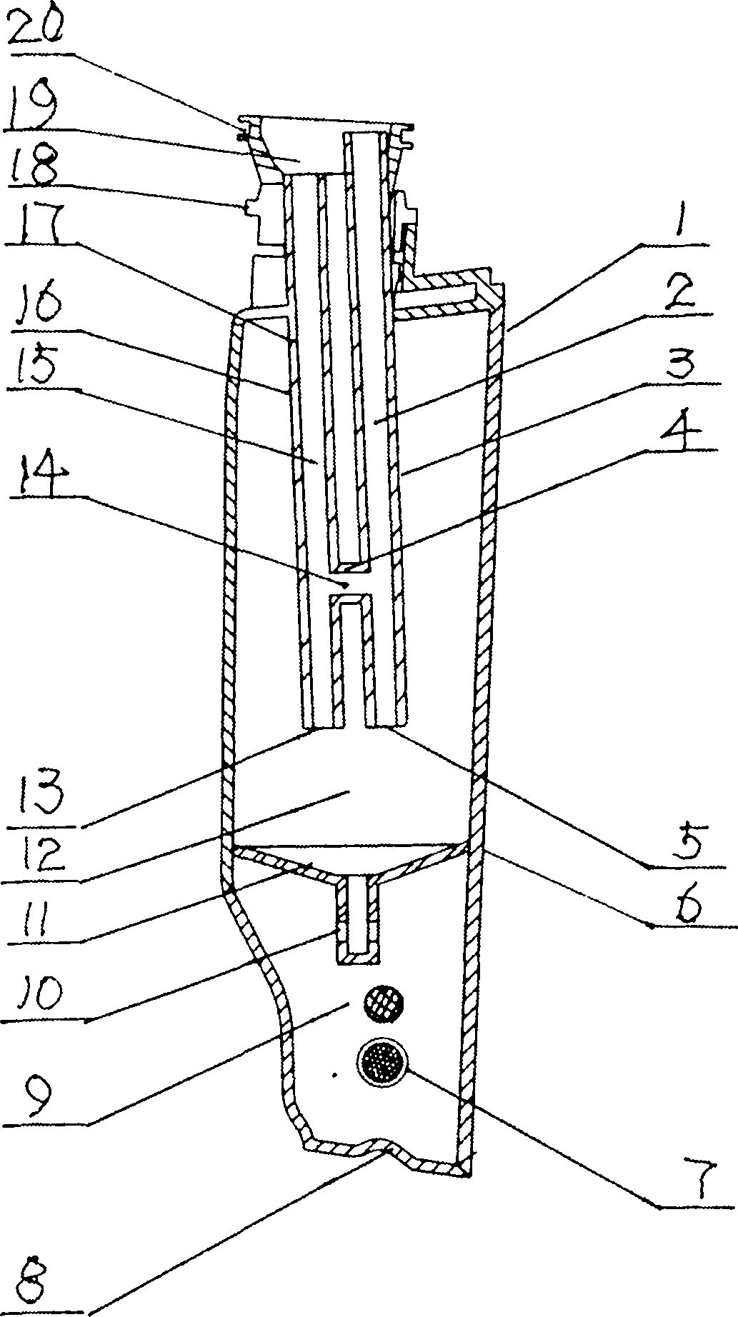
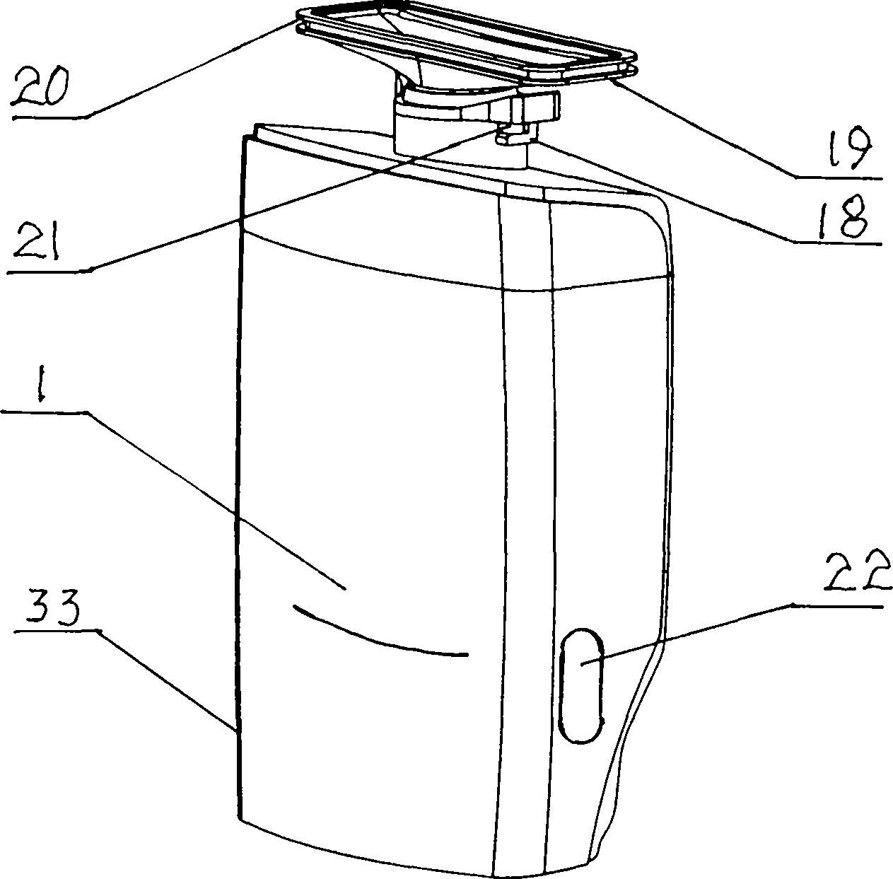
[0017] see figure 1 , figure 2 , image 3 and Figure 4 A kind of liquid recovery box 1, described liquid recovery box 1 is made up of diversion device 17, casing 33 and water storage area funnel 11; The water collecting port fixing ring 18 on the body 33 is rotated and clamped, and the water storage area funnel 11 is installed in the middle and lower part of the liquid recovery tank 1, thereby forming a water storage area 9 between the water storage area funnel 11 and the bottom of the liquid recovery tank 1.

[0018] -The diverter device 11 is a double straight pipe with a water collecting port 19 at one end and a horizontally connecting conduit 4 in the middle. Stoma13.

[0019] - The water leakage hole 10 of the funnel 11 in the water storage area is in the shape of a straight cylinder with a side wall drainage vent.

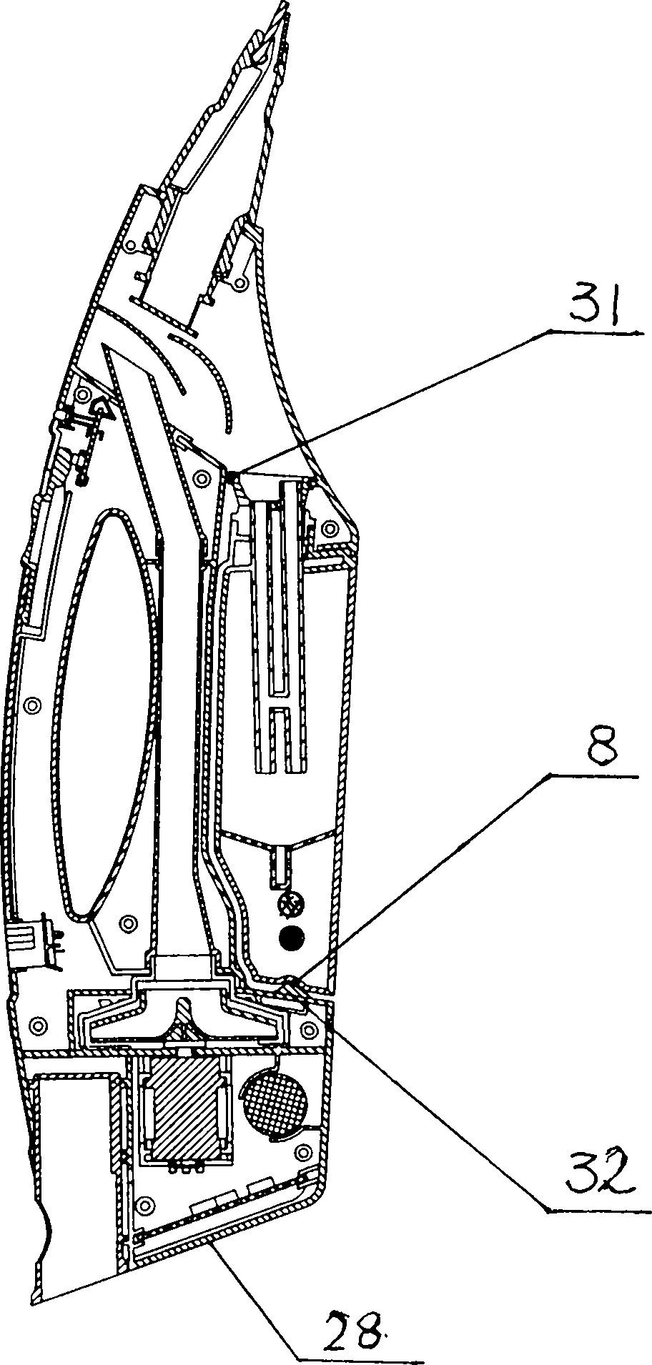
[0020] see image 3 The liquid recovery box 1 is fixedly connected with the water-collection clamp position 31 on the multi-purpose liquid recovery d...


PUM


Abstract

A liquid recycling bin is composed of a division device, a bin body and a hopper of a water storage area. The division device with a water collection port is clamped with a water collection port fixing ring on the bin body in a rotating mode through a water collection port fixing column. The hopper of the water storage area is installed at the lower middle portion inside the liquid recycling bin, so that the water storage area is formed between the hopper of the water storage area and the bottom of the liquid recycling bin. A water storage buffer area is formed between the hopper of the water storage area and the top of the bin body. By means of the liquid recycling bin, it is avoided that due to changes of use positions, recycled liquid flows out in the use process of the liquid recycling bin; even though a small part of liquid flows out of the storage area, the small part of liquid will not flow out of the liquid recycling bin by means of the buffer area, and the use efficiency of the multipurpose liquid recycling bin is improved.

Description

technical field [0001] The invention relates to a device for removing accumulated water on hard surfaces, in particular to a liquid recovery box in a liquid recovery device for removing accumulated water on glass, walls and ground. Background technique [0002] The structure of the water storage and recovery tank of the existing hard surface liquid recovery device is a whole structure, and the collected water is collected into the water storage and recovery tank through the water inlet pipe. Since the water inlet pipe and the vent hole are straight pipes, when the use position changes For example, when it is inverted, the collected liquid will flow back out through the water inlet pipe and the air hole, thereby greatly limiting the scope of use of the existing hard surface liquid recovery device. Contents of the invention [0003] The object of the present invention is to provide a liquid recovery tank used on a liquid recovery device, which can prevent the recovered liqui...

Claims


Application Information

Patent Timeline
IPC IPC(8): A47L1/00A47L1/05
Inventor 宋振宇邓穗文李信祥
Owner 宋振宇
Learn More