
LED (light-emitting diode) display terminal monitoring system

A technology for display terminals and monitoring systems, applied in transmission systems, electrical components, etc., can solve the problems of inability to visually mark the display screen, inability to carry out the display screen, and high labor costs

Inactive Publication Date: 2014-10-29
XIAN NOVASTAR TECH
View PDF5 Cites 11 Cited by
  • Summary
  • Abstract
  • Description
  • Claims
  • Application Information

AI Technical Summary

Problems solved by technology

[0003] At present, most of the monitoring solutions provided by the market adopt manual inspection or regular inspection; during the management process, it is impossible to visually mark each display screen through the position information of the display screen
Therefore, the existing technical solutions have the following disadvantages: (1) the real-time status of the display screen cannot be reflected in time; (2) the labor cost is high; (3) the early warning of the display screen cannot be performed; and (4) the result cannot be obtained based on the position of the display screen show, unintuitive

Method used


Image

  • LED (light-emitting diode) display terminal monitoring system
  • LED (light-emitting diode) display terminal monitoring system
  • LED (light-emitting diode) display terminal monitoring system

Examples


Embodiment Construction

[0021] In order to make the above objects, features and advantages of the present invention more comprehensible, specific implementations of the present invention will be described in detail below in conjunction with the accompanying drawings.

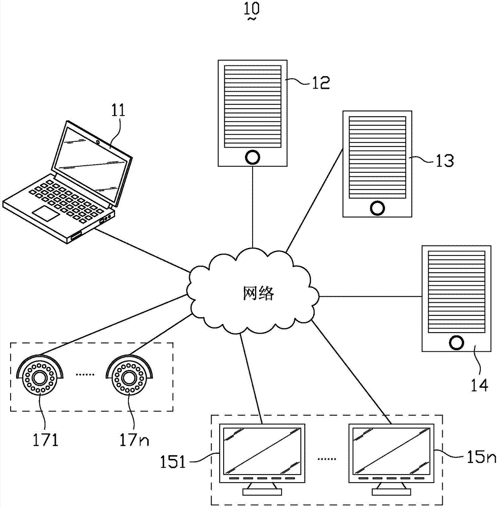
[0022] see figure 1 , the embodiment of the present invention realizes the hardware architecture of LED display terminal monitoring including a client 11, an electronic map server 12, a cloud storage server 13, a monitoring server 14, LED display terminals 151-15n, and camera devices 171-17n; and the client 11 , the electronic map server 12, the cloud storage server 13, the monitoring server 14, the LED display terminals 151-15n and the camera devices 171-17n are connected together through a network.

[0023] Wherein, client 11 is for example personal computer, notebook computer or mobile phone etc., and it is installed with browser, and the user can be connected to monitoring server 14 to show the current status of LED display termina...


PUM


Abstract

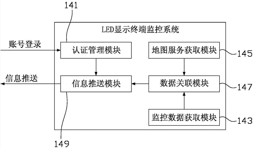
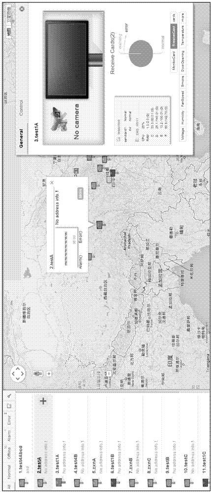
The invention relates to an LED display terminal monitoring system. The LED display terminal monitoring system comprises a certification management module, a map service acquisition module, a data association module and an information push module, wherein the certification management module is used for certifying monitoring permission of a login identification to an LED display terminal; the map service acquisition module is used for acquiring an electronic map; the data association module is used for adding a mark of an LED display terminal to a corresponding position point on the electronic map according to position coordinates information of the LED display terminal which the login identification belongs to and associating monitored data of the LED display terminal which the login identification belongs to to the mark of the LED display terminal; the information push module is used for pushing the electronic map with the mark of the LED display terminal to an browser for displaying and pushing current monitoring data of the LED display terminal associated with the mark of the triggered LED display terminal when a user triggers the mark of the LED display terminal to the browser for being displayed in the mode of a pop-up window. The LED display terminal monitoring system can visually display status such as playing, monitoring, leasing etc. of the LED display terminal and facilitates user timely knowing operating states of every LED display terminal.

Description

technical field [0001] The invention relates to the technical field of LED display monitoring, in particular to an LED display terminal monitoring system. Background technique [0002] Currently, LED (Light Emitting Diode, light-emitting diode) display systems are widely used in urban media and urban traffic electronic signage. In practical applications, users will arrange the LED display system in different geographical locations according to actual needs; moreover, during the normal display process of the display, users have the opportunity to keep abreast of the playback progress, playback status, screen rental and screen advertising time transactions. need. Therefore, how to intuitively and conveniently display these requirements to users is one of the problems to be solved urgently. [0003] At present, most of the monitoring solutions provided by the market adopt manual inspection or regular inspection; during the management process, it is impossible to visually mark...

Claims


Application Information

Patent Timeline
IPC IPC(8): H04L29/08
Inventor 谢林韩丹
Owner XIAN NOVASTAR TECH
Learn More