Discharging machine

A cutting machine and unloading technology, applied in the direction of conveyor objects, transportation and packaging, can solve the problems of low efficiency, complex structure, waste of manpower and material resources, etc.

Active Publication Date: 2014-11-05
江苏省徐州华泰工具有限责任公司
View PDF6 Cites 36 Cited by
  • Summary
  • Abstract
  • Description
  • Claims
  • Application Information

AI Technical Summary

Problems solved by technology

[0002] In the production process of steel balls, most of the existing steel ball blanking devices are complex in structure, cumbersome in action, and high in cost. Relatively backward, most of them use manual blanking, especially when a single steel ball needs to be processed in the next process, the efficiency of manual blanking is extremely low, a waste of manpower and material resources, and it is dangerous

Method used


Image

  • Discharging machine

Examples


Embodiment Construction

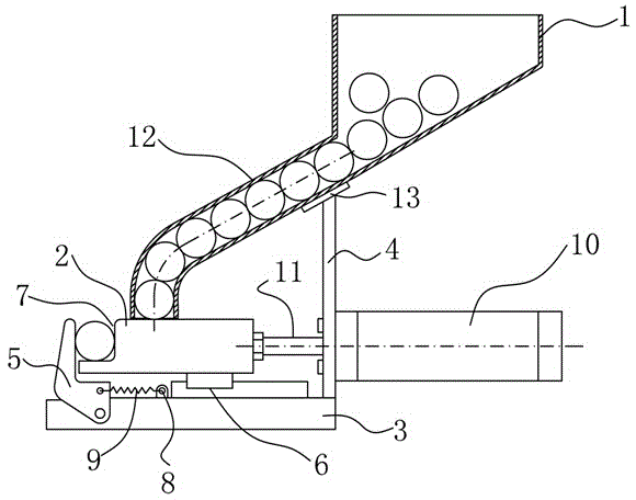
[0014] like figure 1 As shown, a blanking machine described in the embodiment of the present invention is mainly used in the blanking work in the steel ball production line, and mainly includes a main body, a material bin 1 for holding steel balls, a blanking mechanism 2 and a clamping The claw 5, the main body includes a mounting plate 3 and a support plate 4 perpendicular to the mounting plate 3, the unloading mechanism 2 is located on the mounting plate 3 and is connected with the mounting plate 3 through a linear guide rail 6, and one side of the unloading mechanism 2 is provided with The gap 7, the clamping claw 5 is hinged with the mounting plate 3 and forms an accommodation space with the gap 7 of the blanking mechanism 2, and a connecting ear seat 8 is arranged between the clamping claw 5 and the linear guide rail 6, and the clamping claw 5 is connected to the Springs are connected between the lugs 8, and the other side of the blanking mechanism 2 is connected with the...


PUM


Abstract

The invention discloses a discharging machine which comprises a body, a stock bin, a discharging mechanism and a clamping jaw. The body comprises an installation board and a supporting board. The discharging mechanism is connected with the installation board through a linear guide rail. A notch is formed in one side of the discharging mechanism. The clamping jaw is hinged to the installation board and a containing space is formed between the clamping jaw and the notch of the discharging mechanism. A connecting lug base is arranged between the clamping jaw and the linear guide rail. A spring is arranged between the clamping jaw and the connecting lug base. The other side of the discharging mechanism is connected with a piston rod of an air cylinder. An outlet of the stock bin is connected with a conveying pipeline placed obliquely. The top end of the conveying pipeline is fixed to the supporting board and the bottom of the conveying pipeline is perpendicular to the discharging mechanism. The discharging mechanism moves in a reciprocating mode under the effect of the air cylinder, a steel ball to be machined falls in the containing space defined by the discharging mechanism and the clamping jaw under the effect of self-gravity, the clamping jaw is pushed away, so that the steel ball to be machined is conveyed to the designated position of a next working procedure so as to be machined, manpower and material resources are saved, operation is simple, and personal safety of operators is guaranteed.

Description

technical field [0001] The invention relates to the field of steel ball processing, in particular to a cutting machine. Background technique [0002] In the production process of steel balls, most of the existing steel ball blanking devices are complex in structure, cumbersome in action, and high in cost. Relatively backward, most of them use manual blanking, especially when the next process needs to process a single steel ball, the efficiency of manual blanking is extremely low, a waste of manpower and material resources, and it is dangerous. Contents of the invention [0003] In order to solve the above-mentioned technical problems, the present invention provides a blanking machine, which has a simple structure and low cost, is suitable for use in small and medium-sized processing plants, saves manpower and material resources, and can ensure the personal safety of operators at the same time. [0004] The purpose of the present invention is specifically achieved through ...

Claims


Application Information

Patent Timeline
Patent Type & Authority Applications(China)
IPC IPC(8): B65G47/06
Inventor 吴昊
Owner 江苏省徐州华泰工具有限责任公司
Why Eureka
Try Eureka