
Vibration damping fastener for groove type rail of streetcar

A technology for vibration reduction fasteners and trams, applied in the field of rail transit, can solve the problems of weak vibration reduction effect and poor noise reduction ability.

Inactive Publication Date: 2014-11-05
BEIJING JIUZHOUYIGUI SHOCK & VIBRATION ISOLATION
View PDF10 Cites 7 Cited by
  • Summary
  • Abstract
  • Description
  • Claims
  • Application Information

AI Technical Summary

Problems solved by technology

[0003] Although the purpose of the above patent is also a vibration and noise reduction fastener, its vibration reduction effect is weak and its noise reduction ability is relatively poor.

Method used


Image

  • Vibration damping fastener for groove type rail of streetcar
  • Vibration damping fastener for groove type rail of streetcar
  • Vibration damping fastener for groove type rail of streetcar

Examples


Embodiment Construction

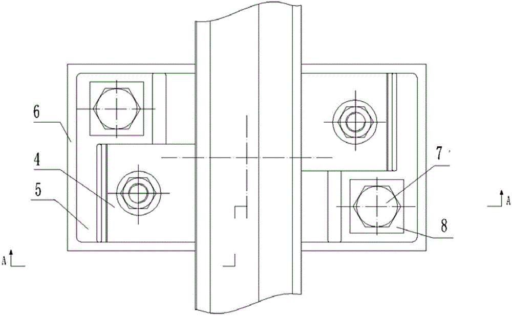
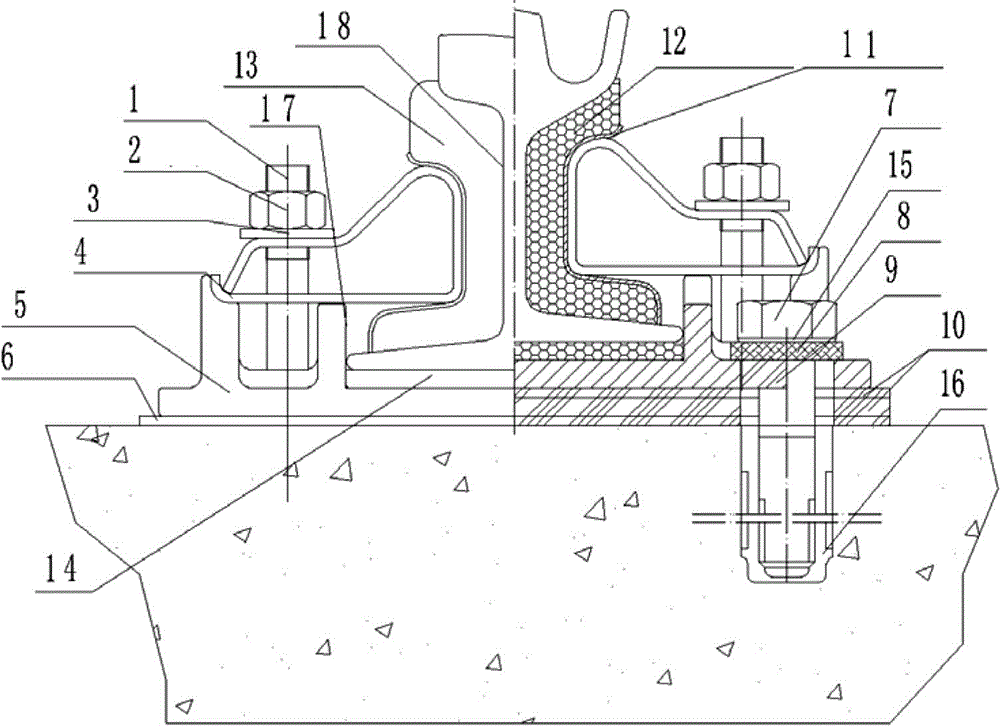
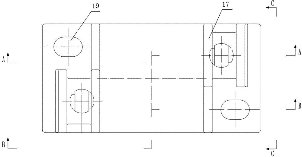
[0018] Such as figure 1 As shown, a vibration-damping fastener for a grooved rail of a tram, including a vibration-damping strip (vibration-damping strip I13 and vibration-damping strip II12) arranged at the waist of the grooved rail and a positioning shrapnel for squeezing and fixing the vibration-damping strip 4. The positioning elastic piece 4 supports the damping strip and fits closely on the waist 18 of the grooved rail. The whole vibration-damping fastener is fixed by oblique bolt sets and anchor bolt sets. The bolt sets include bolts 1, nuts 2 and flat washers 3. The anchor bolt sets include anchor bolts 7 and flat spacers 8. The anchor bolts of the vibration-damping fasteners Fix the positioning shrapnel on the iron backing plate 5. And the iron backing plate 5 is fixed on the sleeper by the bolt set and the anchor bolt set.

[0019] The positioning shrapnel 4 is arranged horizontally and fixed by anchor bolts, and the fixed center line is located away from the end o...


PUM


Abstract

The invention provides a vibration damping fastener for a groove type rail of a streetcar. The vibration damping fastener comprises a vibration damping strip which is arranged at the waist part of the groove type rail, a positioning iron plate and a positioning spring piece which are used for extruding and fixing the vibration damping strip, wherein the positioning spring piece enables the vibration damping strip to be tightly bonded to the waist part of the groove type rail through the positioning iron plate. For the vibration damping fastener for the groove type rail, by adoption of the ingenious design of the shape and the structure of each part and the connection, the multi-stage vibration damping is realized, the rigid connection is reduced, and thereby, and the purposes of reducing the vibration of the rail and reducing the noise pollution are achieved.

Description

technical field [0001] The invention relates to a vibration-damping fastener for a grooved rail of a tram, belonging to the technical field of rail transportation. Background technique [0002] A fastener for tram tracks was disclosed on February 12, 2014 (application number: 201310557574.4), including an iron backing plate, two spring bars, two bolts, two spiral spikes, and a grooved rail The protective mechanism, two fastener covers, the iron backing plate is laid on the base, the grooved rail protection mechanism is symmetrically arranged at the center line of the iron backing plate, the grooved rail is pressed on the grooved rail protection mechanism and the grooved rail protection mechanism is wrapped On the bottom and bottom side of the grooved rail, two bolts and two spiral spikes are respectively arranged on both sides of the grooved rail and are mirror-symmetrical with respect to the grooved rail. The spiral spikes pass through the iron backing plate and penetrate i...

Claims


Application Information

Patent Timeline
IPC IPC(8): E01B21/04E01B19/00E01B9/62
Inventor 房海元邵斌孙燕佟小朋王超高淑华梁国君刘伟李贵花李腾任奇孙方遒曾凡冲周迎春邹长云
Owner BEIJING JIUZHOUYIGUI SHOCK & VIBRATION ISOLATION
Learn More