Real-time reminder method of speed limit on complex road surface and image and laser composite remote sensing road surface monitoring automatic alarm system

An automatic alarm and composite technology, applied in the field of automation, can solve the problems of no detection equipment for road surface slippery coefficient and road surface ice and snow coverage rate, vehicle braking distance becomes larger, real-time modification, etc., to achieve the effect of avoiding major traffic accidents

Active Publication Date: 2018-08-17
西安纳兴电子科技有限公司
View PDF5 Cites 0 Cited by
  • Summary
  • Abstract
  • Description
  • Claims
  • Application Information

AI Technical Summary

Problems solved by technology

[0002] Water, ice, and snow on the road lead to wet and slippery road conditions, especially in winter, when the ice and snow on the road cannot melt in time. When the vehicle is driving, the braking distance of the vehicle will increase, resulting in rear-end collisions. The frequent occurrence of vicious traffic accidents such as serial collisions
The existing traffic sign display board cannot modify the speed limit sign display board in real time according to the road conditions, so that the driver cannot adjust the speed in time according to the road conditions, so as to control the driving speed within the safe driving range
At present, our traffic management department does not have equipment that can detect road surface water, ice accumulation, snow thickness, road surface slippery coefficient, and road surface ice and snow coverage. It cannot automatically monitor road surface conditions, automatically alarm, and modify in real time according to road surface conditions. speed limit sign display board

Method used


Image

  • Real-time reminder method of speed limit on complex road surface and image and laser composite remote sensing road surface monitoring automatic alarm system
  • Real-time reminder method of speed limit on complex road surface and image and laser composite remote sensing road surface monitoring automatic alarm system

Examples


Embodiment Construction

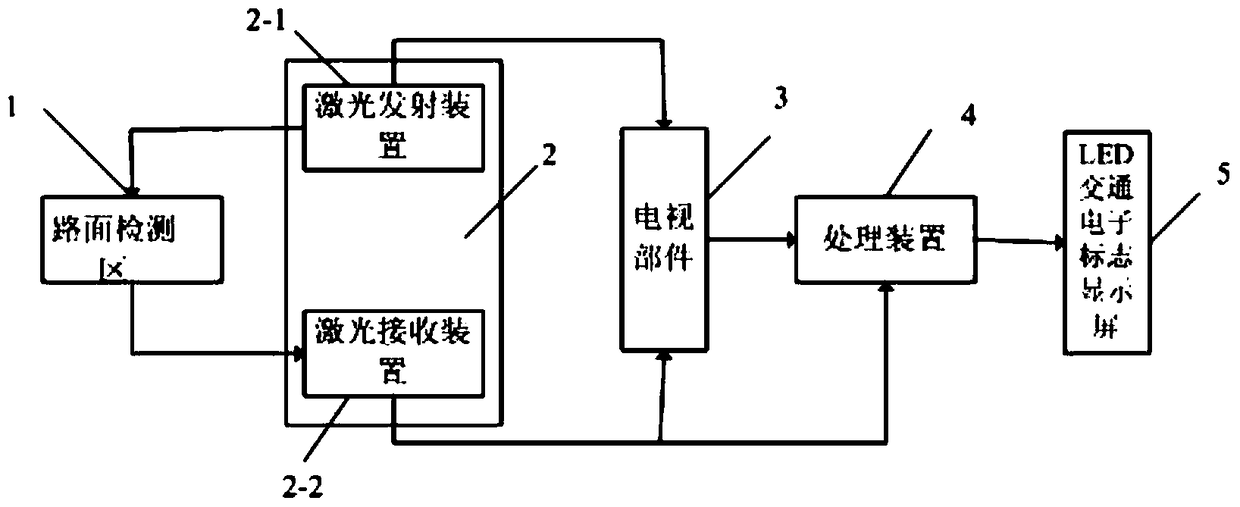
[0017] figure 1 It is a structural schematic diagram of an image and laser composite remote sensing road surface monitoring automatic alarm system of the present invention.

[0018] The real-time reminder method for speed limit on complex roads is characterized in that it is implemented according to the following steps:

[0019] (1) Detection of abnormal road conditions: use sensors to detect abnormal road conditions that affect driving speed; and capture road surface image information;

[0020] (2) Calculate the degree of influence: the abnormal condition of the road surface combined with the image information of the road surface to convert the ice and snow coverage rate to determine the degree of influence of the abnormal condition on the driving speed;

[0021] (3) Calculate the speed limit value: according to the road management regulations, convert the speed limit value under this abnormal situation;

[0022] (4) Real-time warning of speed limit: synchronously display t...


PUM


Abstract

The invention discloses a complex pavement speed limitation real-time prompting method and an image and laser compound type remote sensing pavement monitoring and automatic alarm system. The system comprises a sensor used for emitting and receiving signals of a pavement detection area, a television component used for conversion of snow and ice coverage, a processing device and an LED traffic electronic sign display screen, the sensor comprises a laser emitting device used for emitting lasers to the pavement detection area and a laser receiving device used for receiving laser signals scattered back by the pavement, the laser emitting device is connected with the television component, the television component and the data processing device are in wired connection or wireless connection, and the processing device is connected with the LED traffic electronic sign display screen. The image and laser compound type remote sensing pavement monitoring and automatic alarm system achieves automatic detection on accumulated water, accumulated snow, the thickness of the accumulated snow, the pavement slippery coefficient and the pavement ice and snow coverage of the pavement, can give an alarm in real time and synchronously amends a speed-limiting value of a speed-limiting logo display board.

Description

technical field [0001] The invention belongs to the technical field of automation, in particular to an image and laser composite remote sensing automatic alarm system for road surface monitoring. Background technique [0002] Water, ice, and snow on the road lead to wet and slippery road conditions, especially in winter, when the ice and snow on the road cannot melt in time. When the vehicle is driving, the braking distance of the vehicle will increase, resulting in rear-end collisions. Serial collisions and other vicious traffic accidents occur frequently. The existing traffic sign display board cannot modify the speed limit sign display board in real time according to the road conditions, causing the driver to be unable to adjust the speed of the vehicle in time according to the road conditions, so that the driving speed is controlled within the safe driving range. At present, our traffic management department does not have equipment that can detect road surface water, ic...

Claims


Application Information

Patent Timeline
Patent Type & Authority Patents(China)
IPC IPC(8): G08G1/09G08G1/16
Inventor 罗寰翁兴伟赵辉韩统张蕾蔡亚伟李牧东封普文蚩军祥岳蓓佩张小会傅山力翁欣平
Owner 西安纳兴电子科技有限公司
Why Eureka
Try Eureka