
Battery box

A battery box and battery technology, applied in battery pack components, circuits, electrical components, etc., can solve problems such as increasing workload, damaging socket connectors, occupying effective space in battery boxes, etc., to improve work efficiency, fast positioning, The effect of increasing strength

Active Publication Date: 2014-11-05
中创新航科技股份有限公司
View PDF4 Cites 10 Cited by
  • Summary
  • Abstract
  • Description
  • Claims
  • Application Information

AI Technical Summary

Problems solved by technology

[0003] The structure of the lithium-ion battery box used on the existing electric vehicle is as the battery box structure disclosed in the Chinese patent application "A Power Lithium Battery Box" with the publication number CN 103000845A. Box body, the box body includes a top cover, a bottom plate and a side wall between the top cover and the bottom plate, a socket connector for communicating with the user is arranged on the surface of the box body, and the end of the socket connector is far away from the surface of the box body It protrudes from the surface of the box where it is located, so it is possible to collide with foreign objects during the moving of the battery box and damage the socket connector, and when the socket connector is connected to the plug connector that matches it for communication, the plug The connector will extend outside the box. This structure will not only occupy the effective space outside the battery box, but also easily collide with other structures outside the box. After the collision, the plug connector and socket connector may be damaged. It affects the normal transmission of signals, and even needs to replace the socket connector or plug connector, which increases the workload and affects the installation efficiency of the battery line

Method used


Image

  • Battery box
  • Battery box
  • Battery box

Examples


Embodiment Construction

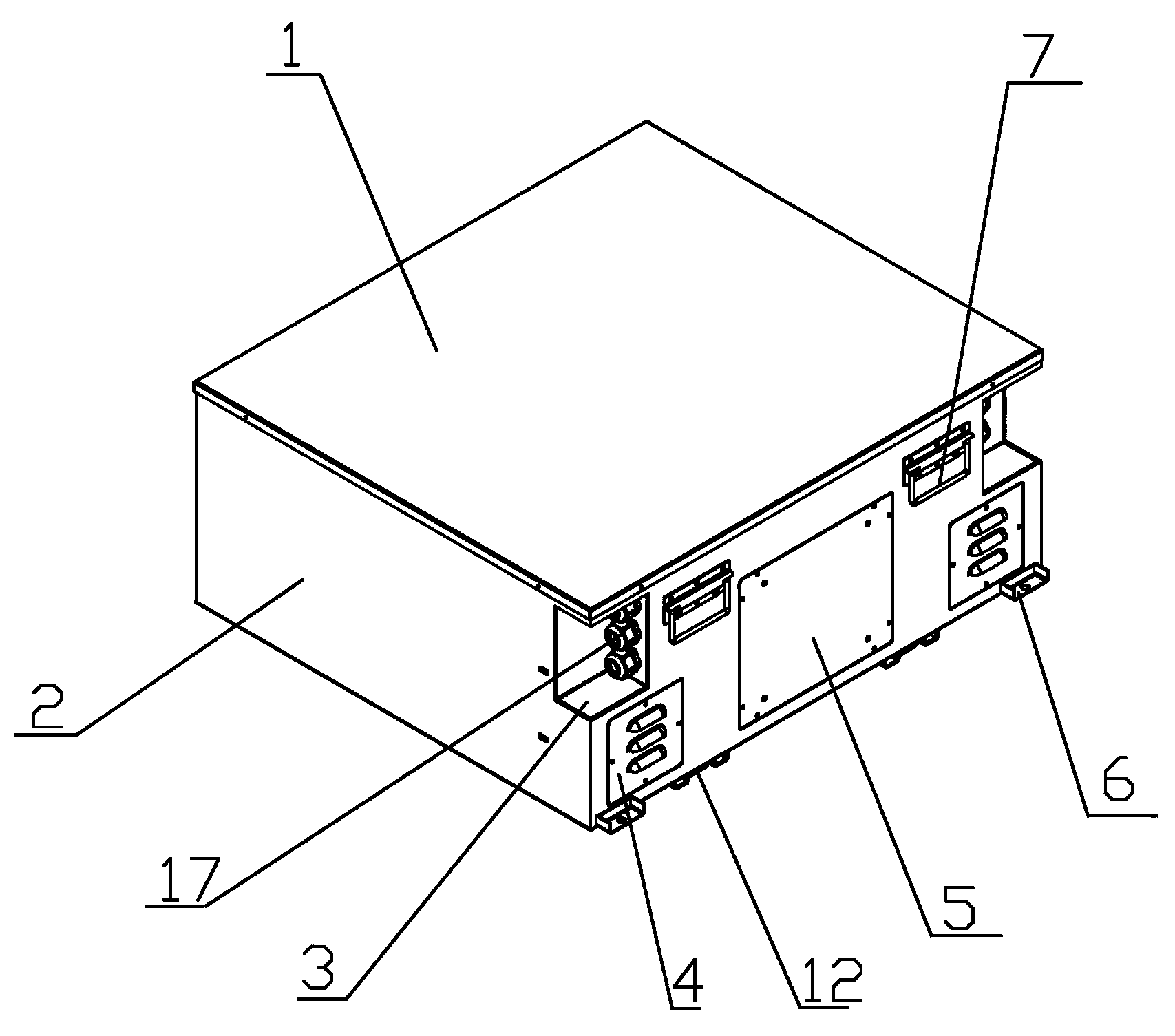
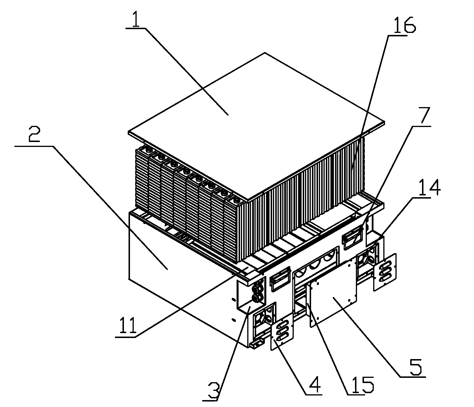
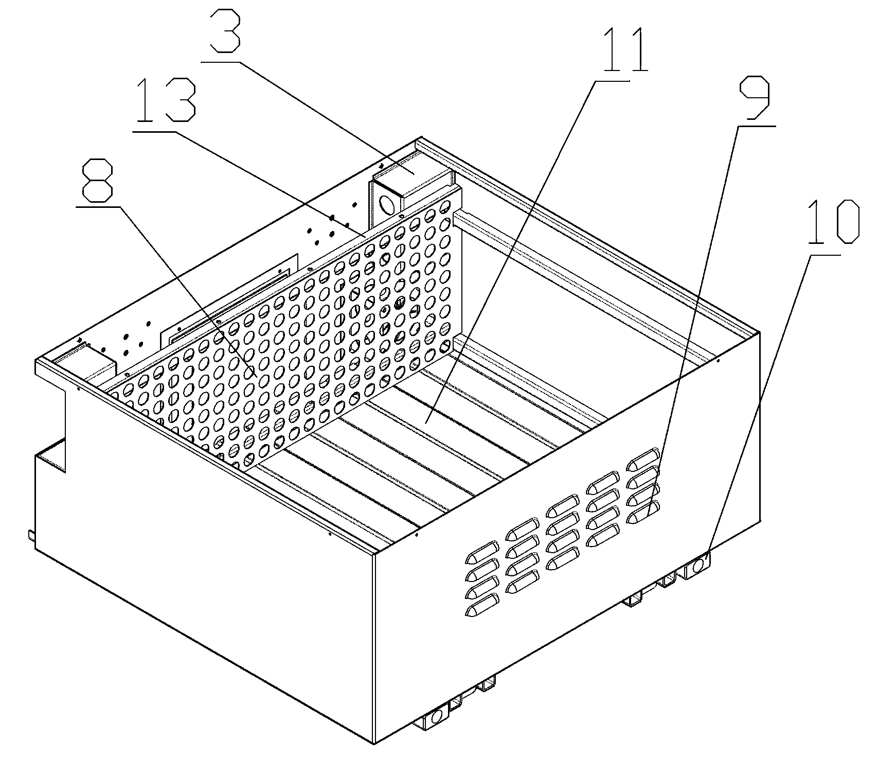
[0030] Embodiments of the battery box of the present invention: as Figure 1 to Figure 5 As shown, the battery box includes a box body 2, and the box body 2 includes a top cover 1, a bottom plate, and surrounding side walls that are arranged between the top cover and the bottom plate, and the side walls include front side walls, rear side walls, Left side wall and right side wall, box body 2 is provided with dividing plate 8, and the upper and lower end of dividing plate 8 is respectively provided with the reinforcement crossbeam 13 that is used to increase the intensity of dividing plate 8, and dividing plate 8 divides the inner space of box body 2 into There are two relatively independent spaces at the front and rear. The front space is the cooling management system space for placing the fan 14 and the management system 15. The rear space is the battery storage space for the battery. The ventilation holes for air circulation between the space and the cooling management syste...


PUM


Abstract

The invention relates to a battery box, comprising a box body and a socket connector arranged on the surface of the box body and used for transmitting electrical signals to the outside, wherein the surface of the box body is provided with a groove, the socket connector is arranged on the wall of the groove and has a bottom end close to the groove wall and a top end far away from the groove wall, and the top end of the socket connector is lower than the surface of the box body located at the periphery of the groove. During collision of the battery box with an outer object, the socket connector is hardly damaged, so replacing frequency of the socket connector is lowered down, work efficiency is improved, and cost is reduced; meanwhile, when a pin connector is used for plug-in electric connection with the socket connector, the distance between the pin connector and the surface of the box body and the distance that the bending radius of a signal line extends to the surface of the box body are reduced, so occupation of effective space out of the battery box is reduced.

Description

technical field [0001] The invention relates to a battery box. Background technique [0002] Lithium-ion batteries are widely used in portable communication, vehicle power and grid energy storage due to their advantages of high voltage, large capacity, small size, light weight and wide operating temperature range, especially in the field of electric vehicles. [0003] The structure of the lithium-ion battery box used on the existing electric vehicle is like the battery box structure disclosed in the Chinese patent application "A Power Lithium Battery Box" with the publication number CN 103000845A. The box body, the box body includes a top cover, a bottom plate and a side wall between the top cover and the bottom plate, and a socket connector for communicating with the user is arranged on the surface of the box body, and the end of the socket connector is far away from the surface of the box body It protrudes from the surface of the box where it is located, so it is possible...

Claims


Application Information

Patent Timeline
IPC IPC(8): H01M2/02H01M2/10H01M2/04H01M50/204H01M50/242H01M50/244
CPCH01M50/20H01M50/502Y02E60/10
Inventor 毛占稳杨振鹏岳秀廷刘宇强张辉李炜
Owner 中创新航科技股份有限公司
Learn More