
Winding buffering mechanism and winching device

A technology of buffer mechanism and hoisting device, applied in the direction of hoisting device, spring mechanism, etc., can solve the problems of unfavorable protection of self-bending wind grille, unfavorable protection of self and bending wind grille, etc., to achieve safe use and avoid damage to equipment Effect

Active Publication Date: 2014-11-12
GUANGDONG SHUNDE TIMBERY TECH GLASS
View PDF6 Cites 4 Cited by
  • Summary
  • Abstract
  • Description
  • Claims
  • Application Information

AI Technical Summary

Problems solved by technology

[0004] Based on this, it is necessary to provide a hoisting buffer mechanism for the problem that the current hoisting device is not conducive to protecting itself and the curved wind grid. When it is connected between the driving source and the driven object, the hoisting buffer mechanism can effectively Within the stroke range, the driven object can be prevented from being damaged by the force outside the limit, and the drive can be stopped within the effective stroke range of the hoisting buffer mechanism to protect the driving source and the driven object, and play a role of safety protection
[0005] In addition, it is necessary to provide a hoisting device that is safe to use in view of the problem that the current hoisting device is not conducive to protecting itself and the curved wind grille

Method used


Image

  • Winding buffering mechanism and winching device
  • Winding buffering mechanism and winching device
  • Winding buffering mechanism and winching device

Examples


Embodiment 1

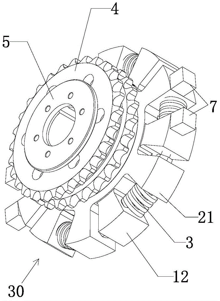
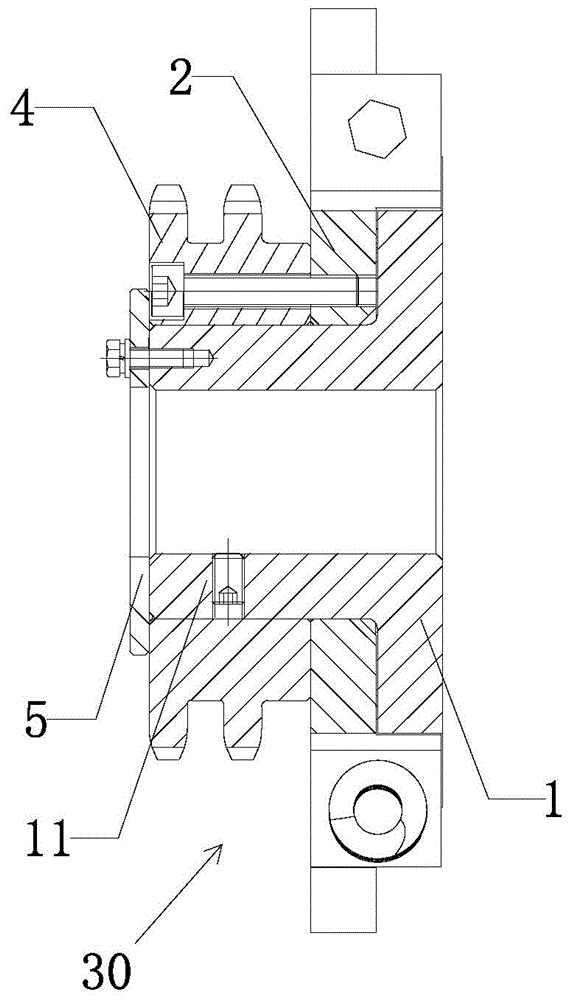
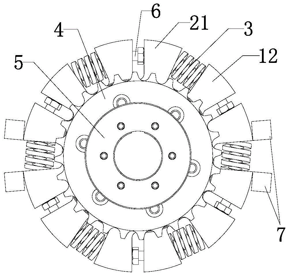
[0028] Such as Figure 1 to Figure 5 As shown, the hoisting buffer mechanism 30 includes a first transmission disc 1, a second transmission disc 2, six buffer elastic members 3, a driven sprocket 4 and an end cover 5, and the first transmission disc 1 is provided with a center extending The central axis 11 and six first moment arms 12 distributed along the periphery, the second transmission disc 2 is provided with six second moment arms 21 corresponding to the first moment arms 12 distributed along the periphery, the second transmission disc 2 Rotatably sheathed on the central shaft 11, the six first moment arms 12 and the six second moment arms 21 intersect each other, and the corresponding first moment arms 12 and the second moment arms 21 are adjacent in position. A cushioning elastic member 3 is provided in the intersecting space between the first moment arm 12 and the second moment arm 21, and the two ends of the buffer elastic member 3 abut against the corresponding firs...

Embodiment 2

[0034] combine Figure 1 to Figure 7, the hoisting device, including the drive motor 10, the fixed base 20 and the hoisting buffer mechanism 30; the fixed base 20 is provided with a rotatable first hoisting shaft 201, a second hoisting shaft 202 and a drive shaft 203, the first The hoisting shaft 201 is connected to the first connecting piece 40, the second hoisting shaft 202 is connected to the second connecting piece 41, and the transmission shaft 203 is connected to the first hoisting shaft 201 and the second hoisting shaft 202; the hoisting buffer mechanism 30 includes a first transmission disc 1, a second transmission disc 2, six buffer elastic members 3, a driven sprocket 4 and an end cover 5. The first transmission disc 1 is provided with a central axis 11 extending along the center and distributed along the periphery. Six first moment arms 12, the second transmission disc 2 is provided with six second moment arms 21 corresponding to the first moment arms 12 distributed...


PUM


Abstract

The invention relates to a winding buffering mechanism and a winding device. The winding buffering mechanism comprises a first driving disc, a second driving disc and buffering elastic pieces, the first driving disc is provided with a center shaft and N first force arms distributed circumferentially, N is a positive integer, the second driving disc is circumferentially provided with N second force arms corresponding to the first force arms in a one-to-one mode, the second driving disc can be rotatably arranged on the center shaft in a sleeved mode, the N first force arms are mutually crossed with the N second force arms, each first force arm and the corresponding second force arm are adjacent in position, the buffering elastic pieces are arranged in spaces respectively formed after each first force arm and the corresponding second force arm are crossed, and the two ends of each buffering elastic piece abut against the corresponding first force arm and the corresponding second force arm respectively. The winding buffering mechanism performs a safety protection function.

Description

technical field [0001] The invention relates to a hoisting buffer mechanism and a hoisting device. Background technique [0002] The production of curved tempered glass is obtained by heating the glass to the softening point in the furnace, then bending it into the curved air grid and then blowing and quenching to form it. After entering the air grid, the two ends of the curved air grid are lifted by the hoisting device to make it bend and shape. At present, the hoisting device includes a driving source and two hoisting shafts, the driving source drives and connects the two hoisting shafts, and each hoisting shaft is provided with a chain for connecting with a curved wind grid. The working principle of the hoisting device is: connect the chains of the two hoisting shafts to the two ends of the curved wind grid respectively, the middle of the curved wind grid is fixed, the driving source drives the two hoisting shafts to rotate, and the two hoisting shafts Turn and wind the...

Claims


Application Information

Patent Timeline
Patent Type & Authority Applications(China)
IPC IPC(8): B66D1/54B66D1/56
Inventor 黎和标
Owner GUANGDONG SHUNDE TIMBERY TECH GLASS
Learn More