Camshaft structure

A camshaft and shaft technology, applied in valve devices, machines/engines, mechanical equipment, etc., can solve problems such as unfavorable energy saving, fuel consumption, frequent replacement, etc., to improve stability and service life, reduce wear, and improve heat dissipation. effect of effect

Active Publication Date: 2014-11-12
TAIZHOU HONGXIANG POWER MACHINERY
View PDF6 Cites 1 Cited by
  • Summary
  • Abstract
  • Description
  • Claims
  • Application Information

AI Technical Summary

Problems solved by technology

[0002] The camshaft is an important part of a piston engine. Its function is to control the opening and closing of the valve. Although the speed of the camshaft in a four-stroke engine is half that of the crankshaft, it usually needs to bear a large torque, so the camshaft needs to be required. Shaft strength and support performance should be high, because the valve movement law is related to the power and operation characteristics of an engine, so it occupies a very important position, and in the process of use, the wear and tear is relatively large, which leads to more frequent replacement and more It consumes fuel to a large extent. In recent years, the problem of energy shortage has become more and more serious, and the price of raw materials and oil has continued to rise, which is not conducive to energy conservation. Therefore, it is extremely important to improve the economy of the engine on the premise of ensuring engine performance. Reducing friction is also a design A question that must be considered when camshaft

Method used


Image

  • Camshaft structure

Examples


Embodiment Construction

[0012] The present invention is described in further detail now in conjunction with accompanying drawing. These drawings are all simplified schematic diagrams, which only illustrate the basic structure of the present invention in a schematic manner, so they only show the configurations related to the present invention.

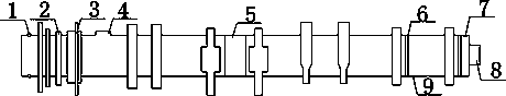
[0013] like figure 1 The preferred embodiment of the camshaft structure of the present invention shown includes a camshaft body 9, and one end of the camshaft body 9 is provided with a concave hole 1 into which the rotating shaft of a power supply is inserted, and there are two concave holes 1, which are arranged symmetrically up and down. 9 Located at one end of the concave hole 1 and near the concave hole 1, there is a first bearing seat 2, the first bearing seat 2 is bonded on the camshaft body 9, and also includes a second bearing seat 5, which is connected to the camshaft The body 9 is bonded, the first bearing seat 2 and the second bearing seat 5 are se...


PUM


Abstract

The invention discloses a camshaft structure which comprises a camshaft body, wherein two concave holes allowing a motor rotating shaft to be inserted are formed in one end of the camshaft body in a vertically symmetrical manner; a first bearing block is arranged at the end, where the concave holes are located, of the camshaft body, is close to the concave holes and is bonded onto the camshaft body; the camshaft structure further comprises a second bearing block which is bonded with the camshaft body; a first bearing and a second bearing are in seal connection in the first bearing block and the second bearing block; an eccentric wheel is arranged between the first bearing block and the second bearing block and located on the upper end surface of the camshaft body; a groove is formed in the position, corresponding to the eccentric wheel, of the camshaft body; and the eccentric wheel is arranged in the groove. The camshaft structure can have a rotation prevention function when bearing torsional force and can obtain good lubrication, the radiating effect is improved, wear of a work surface of a tappet is reduced, certain adjustment can be performed on the tappet simultaneously, besides, the stability of the camshaft is improved, and the service life of the camshaft is prolonged.

Description

technical field [0001] The invention relates to a mechanical component, in particular to a camshaft structure. Background technique [0002] The camshaft is an important part in a piston engine. Its function is to control the opening and closing of the valve. Although the speed of the camshaft in a four-stroke engine is half that of the crankshaft, it usually needs to bear a large torque, so the camshaft needs to be required. Shaft strength and support performance should be high, because the valve movement law is related to the power and operation characteristics of an engine, so it occupies a very important position, and in the process of use, the wear and tear is relatively large, which leads to more frequent replacement and more It consumes fuel to a large extent. In recent years, the problem of energy shortage has become more and more serious, and the price of raw materials and oil has continued to rise, which is not conducive to energy conservation. Therefore, it is ext...

Claims


Application Information

Patent Timeline
Patent Type & Authority Applications(China)
IPC IPC(8): F01L1/047
Inventor 缪家戌
Owner TAIZHOU HONGXIANG POWER MACHINERY
Why Eureka
Try Eureka