Fixed type constant velocity joint

A constant velocity joint and torque transmission technology, applied in the field of constant velocity joints, can solve problems such as the difficulty of assembling fixed constant velocity joints, and achieve sufficient rigidity and ensure rigidity

Active Publication Date: 2014-11-12
HONDA MOTOR CO LTD
View PDF6 Cites 1 Cited by
  • Summary
  • Abstract
  • Description
  • Claims
  • Application Information

AI Technical Summary

Problems solved by technology

Of course, in this case, it is difficult to tilt the holder 18, and as a result, it becomes difficult to assemble the fixed type constant velocity joint 10.

Method used


Image

  • Fixed type constant velocity joint
  • Fixed type constant velocity joint
  • Fixed type constant velocity joint

Examples


Embodiment Construction

[0043] Hereinafter, preferred embodiments will be cited, and the fixed type constant velocity joint according to the present invention will be described in detail with reference to the drawings. In addition, for easy understanding, the torque transmission ball and drive shaft are attached with Figure 7 ~ Figure 11 The attached reference numerals are the same reference numerals.

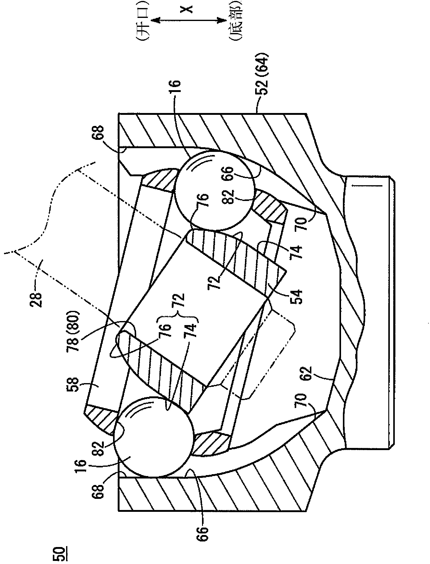
[0044] figure 1 It is a schematic cross-sectional view of main parts in a state where an operating angle is generated in the fixed constant velocity joint 50 according to the embodiment of the present invention. The fixed constant velocity joint 50 has an outer member 52 , an inner member 54 , a torque transmission ball 16 interposed between the outer member 52 and the inner member 54 , and a retainer 58 holding the torque transmission ball 16 .

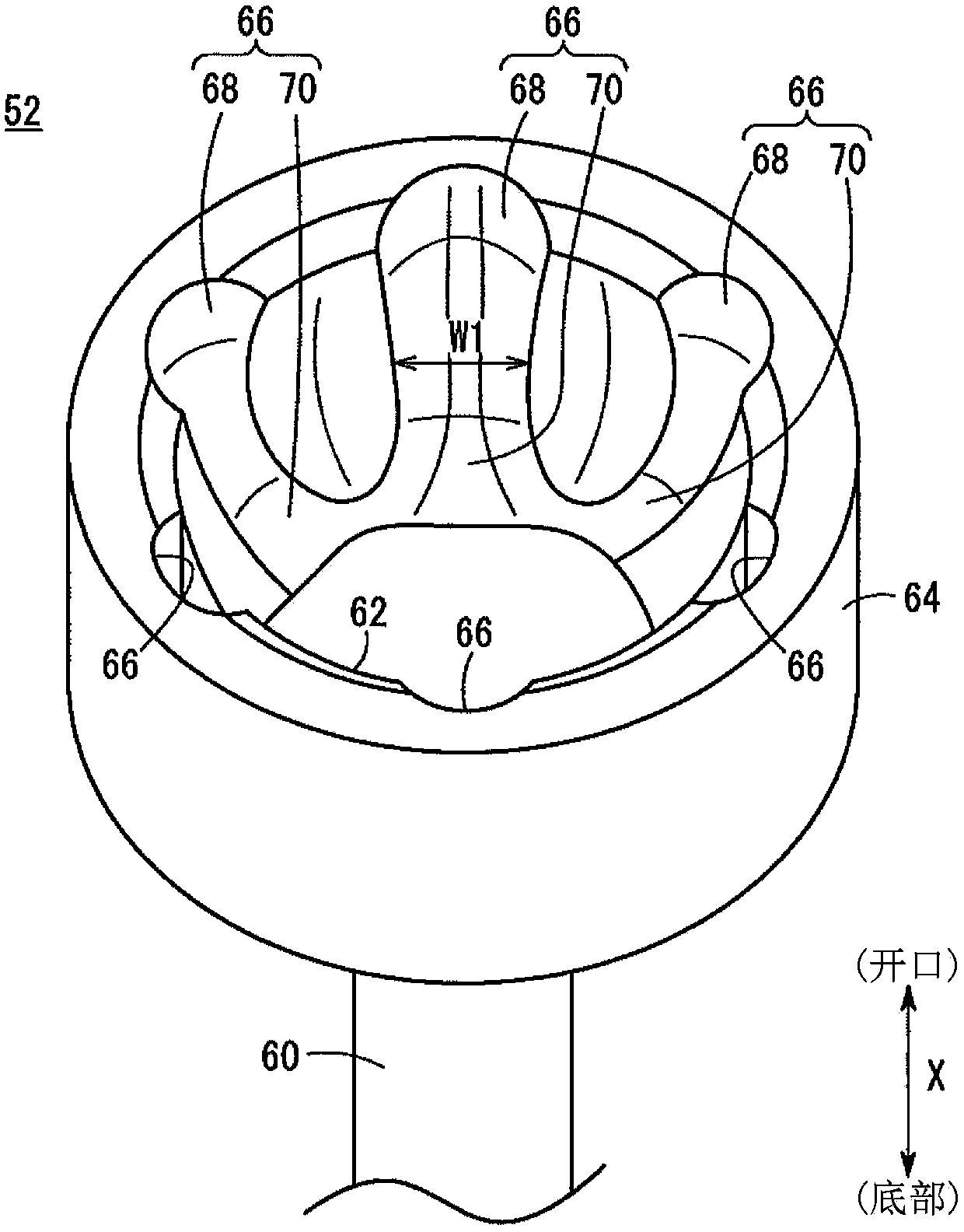
[0045] figure 2 It is a schematic perspective view of main parts of the outer member 52 . in addition, figure 1 and figure 2 Arrow X in , indicat...


PUM


Abstract

The invention relates to a fixed type constant velocity joint (50). A bottomed hole (62) for inserting an inner member (54) and a retainer (58) is provided in an outer member (52) forming the fixed type constant velocity joint (50). On the inner wall of the bottomed hole (62), an outer side ball groove (66) for allowing a torque transmission ball (16) to slide is provided in a manner of extending from the opening side to the bottom side of the bottomed hole (62). The outer side ball groove (66) is formed by a first groove (68) and a second groove (70) which is connected with the first groove (68) and wide in width compared with the first groove (68), for example, the first groove (68) is positioned at the opening side of the bottomed hole (62), and the second groove (70) is positioned at the bottom side of the bottomed hole (62). The torque transmission ball (16) slides in the first groove (68) without entering into the second groove (70) when a rotating shaft (28) is in a range of an angle of inclination.

Description

technical field [0001] The present invention relates to a fixed type constant velocity joint for transmitting rotational driving force from a rotating shaft to another rotating shaft. Background technique [0002] The traveling driving force transmission mechanism of an automobile is configured to have two constant velocity joints as joints for transmitting rotational driving force from a rotating shaft to another rotating shaft. Generally, one of the two constant velocity joints is a sliding type joint that allows the rotating shaft to be displaced along the length direction of a bottomed hole formed in the outer member, and the remaining one is a joint that allows the rotating shaft to A fixed type joint with a slope in the bottom hole. Fixed constant velocity joints are generally set between the drive shaft and the hub. [0003] Figure 7 A schematic overall front view of the fixed constant velocity joint 10 is shown. The fixed constant velocity joint 10 has an outer m...

Claims


Application Information

Patent Timeline
Patent Type & Authority Applications(China)
IPC IPC(8): F16D3/223
Inventor 榊原泰辅村上贵文
Owner HONDA MOTOR CO LTD
Why Eureka
Try Eureka