Explosive connecting rod and engine

A technology of connecting rod and connecting rod cover, which is applied in the direction of connecting rod, mechanical equipment, shaft and bearing, etc., can solve the problems of high mechanical power, large weight and large size, so as to improve the mechanical efficiency, improve the stress condition, reduce the The effect of weight

Active Publication Date: 2021-11-19
WEICHAI POWER CO LTD
View PDF7 Cites 0 Cited by
  • Summary
  • Abstract
  • Description
  • Claims
  • Application Information

AI Technical Summary

Problems solved by technology

However, the dimension of the connecting rod with flat cut is large in the width direction and the weight is large, resulting in a large consumption of mechanical power. Therefore, when the installation space is limited, the connecting rod with oblique cut is used. Due to the large centrifugal force, the bolts connecting the connecting rod cover and the big end of the connecting rod bear a large shear force, and the force of the two bolts is uneven, so the force of the connecting rod with oblique cuts is not good.

Method used


Image

  • Explosive connecting rod and engine
  • Explosive connecting rod and engine
  • Explosive connecting rod and engine

Examples


Embodiment Construction

[0025] In order to make the technical problems solved by the present invention, the technical solutions adopted and the technical effects achieved clearer, the technical solutions of the present invention will be further described below in conjunction with the accompanying drawings and through specific implementation methods. It should be understood that the specific embodiments described here are only used to explain the present invention, but not to limit the present invention. In addition, it should be noted that, for the convenience of description, only the parts related to the present invention are shown in the drawings but not all of them.

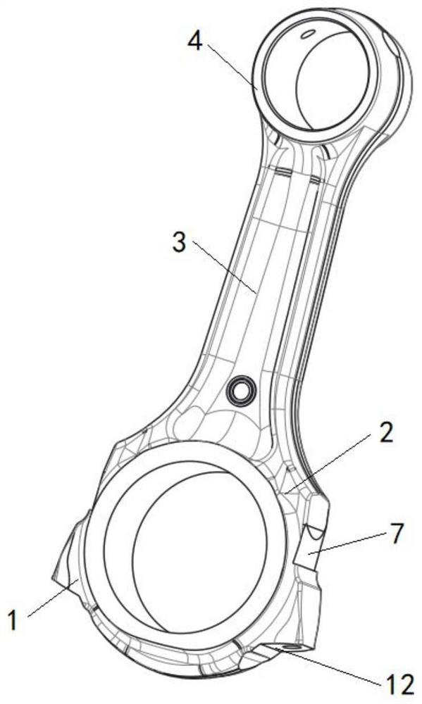
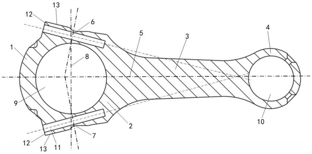
[0026] Such as Figure 1 to Figure 3 As shown, the present embodiment provides a broken connecting rod, including a connecting rod body and a connecting rod cover 1, and the connecting rod body includes a connecting rod big end part 2, a connecting rod small end 4 and a connecting rod big end part 2 and The connecting rod body 3 of ...


PUM


Abstract

The invention relates to the field of engines, and discloses a broken connecting rod and an engine. The central axis of the big head of the connecting rod and the central axis of the small head of the connecting rod form a central plane of the connecting rod; Symmetrical beveled surface, along the direction from the small end of the connecting rod to the large end of the connecting rod, the distance from the beveled surface to the central plane of the connecting rod gradually decreases, and the intersection line of the extension surfaces of the two beveled surfaces is located on the central plane of the connecting rod and parallel to the connecting rod. The central axis of the small head of the rod. The oblique section is distributed symmetrically with respect to the central plane of the connecting rod, and the distance from the oblique section to the central plane of the connecting rod gradually decreases along the direction from the small end of the connecting rod to the small end of the connecting rod, which reduces the dimension in the width direction of the connecting rod to meet the engine installation requirements. The space is limited; the weight of the connecting rod is reduced, and the mechanical efficiency is improved; the intersection line of the extension surfaces of the two inclined planes is located on the central plane of the connecting rod and parallel to the central axis of the small end of the connecting rod, and the large end of the connecting rod is stressed Evenly, the force situation of the broken connecting rod is improved.

Description

technical field [0001] The invention relates to the field of engines, in particular to a snap-off connecting rod and an engine. Background technique [0002] The connecting rod is a tool that connects the piston and the crankshaft, transmits the force acting on the piston to the crankshaft, and converts the reciprocating motion of the piston into the rotational motion of the crankshaft. The connecting rod includes a connecting rod body and a connecting rod cover. The connecting rod body includes a connecting rod big end connected to the crankshaft, a connecting rod small end connected to the piston pin, and a connecting rod body connecting the connecting rod big end and the connecting rod small end. , the big end of the connecting rod and the connecting rod cover are connected by bolts to form the big end of the connecting rod. [0003] Connecting rods mainly include flat notch connecting rods and oblique notch connecting rods. Among them, the flat notch connecting rod has ...

Claims


Application Information

Patent Timeline
Patent Type & Authority Patents(China)
IPC IPC(8): F16C7/02
CPCF16C7/02
Inventor 陈秀梅韩景峰祁同晖
Owner WEICHAI POWER CO LTD
Why Eureka
Try Eureka