heat sink

A technology for radiators and heat sinks, which is applied in indirect heat exchangers, heat exchange equipment, electric solid devices, etc., and can solve the problem of insufficient return characteristics of liquid-phase working fluid, reduced heat transfer characteristics of radiator heat pipe groups, and cooling of heat sinks. Efficiency reduction and other problems, to achieve the effect of excellent reflow characteristics, excellent cooling performance, and increased heat absorption

Active Publication Date: 2021-02-26
FURUKAWA ELECTRIC CO LTD
View PDF1 Cites 0 Cited by
  • Summary
  • Abstract
  • Description
  • Claims
  • Application Information

AI Technical Summary

Problems solved by technology

In the heat pipe type radiator, if the heat receiving part of the radiator is arranged above the heat dissipation part in the direction of gravity, the reflux characteristics of the liquid-phase working fluid in the heat pipe are not sufficient, and the evaporation part and the condensation part of the heat pipe group Insufficient volume of the heat pipe group, thus reducing the heat transfer characteristics of the heat pipe group
Therefore, if the heat pipes are arranged horizontally and the heat pipes are connected above the heat sink in the direction of gravity in order to prevent the heat transfer characteristics of the heat pipe group from deteriorating while reducing the space occupied by the radiator, the cooling efficiency of the heat sink will be reduced. reduced, so there is still room for improvement in the cooling characteristics of the heatsink

Method used


Image

  • heat sink
  • heat sink
  • heat sink

Examples


Embodiment Construction

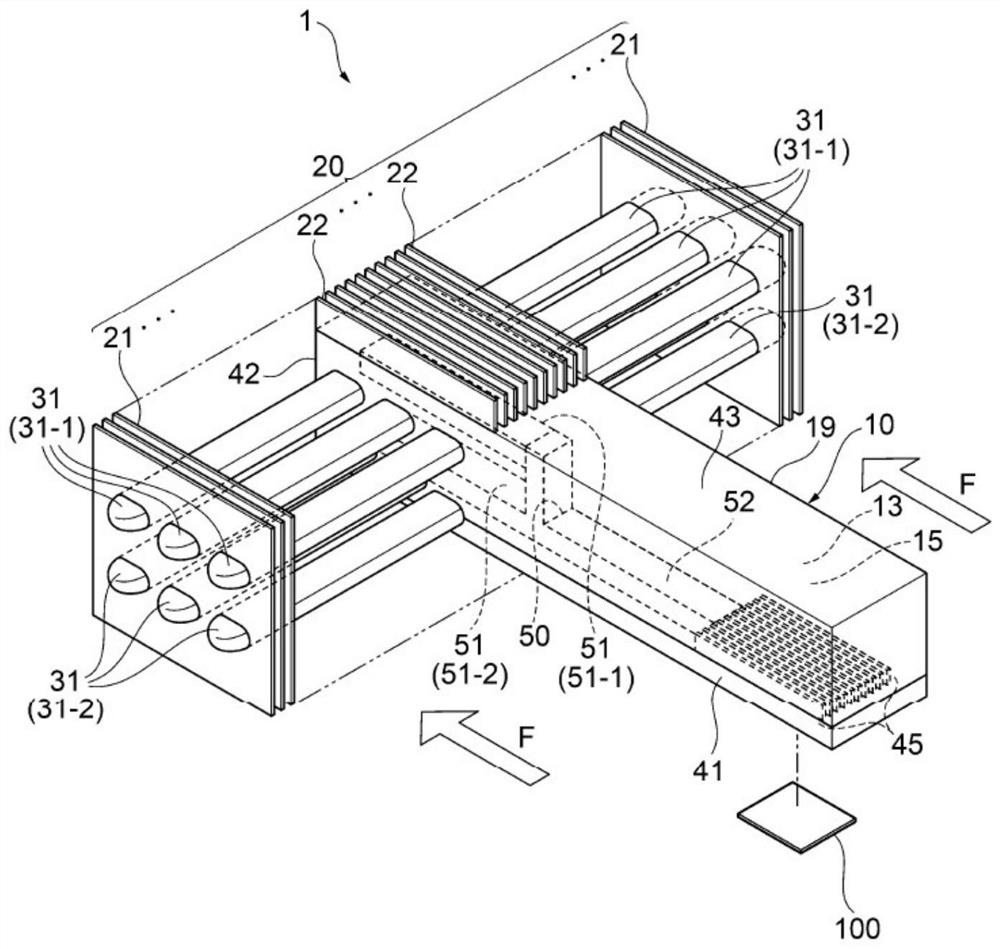
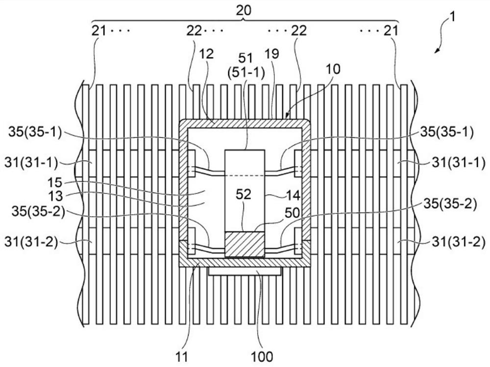
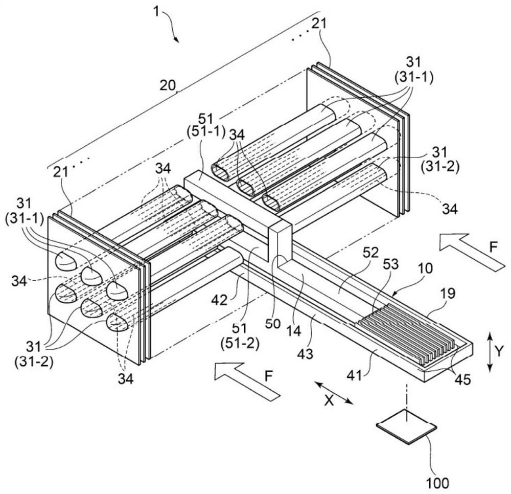
[0041]Hereinafter, the heat sink according to the embodiment of the present invention will be described with reference to the drawings.figure 1 It is an external perspective view explaining the schematic structure of the heat sink according to the embodiment of the present invention.figure 2 It is a front cross-sectional view illustrating a schematic structure inside the heat sink according to the embodiment of the present invention.image 3 It is a perspective view explaining a schematic structure inside the heat sink according to the embodiment of the present invention.Figure 4 It is a plan sectional view explaining a schematic structure inside the heat sink according to the embodiment of the present invention.

[0042]Such asfigure 1 As shown, the radiator 1 involved in the embodiment of the present invention includes: a heat transfer member 10 having a heat receiving portion 41 thermally connected to a heating element 100; a tube body 31 connected to a heat dissipation portion 42 of...


PUM


Abstract

The present invention provides a radiator which can improve the cooling efficiency of the fins regardless of the installation form of the radiator, exhibit excellent cooling performance for a cooling object, and can be installed even in a narrow space. The radiator includes: a heat transfer member, which has a heat receiving portion thermally connected to the heating body, and has a first liquid absorbing core structure; a pipe body, which is connected to the heat insulation portion or the heat dissipation portion of the heat transfer member, and has a second liquid-absorbing wick structure; a heat-dissipating fin group, which is thermally connected to the tube body and is provided with a plurality of heat-dissipating fins; the heat-transfer member has an integral inner space, which communicates from the heat-receiving portion to the The connection part to which the pipe body is connected is sealed with a working fluid, and the inner space of the heat transfer member communicates with the inner space of the pipe body, and the first liquid absorbent core structure has an inner space on the heat transfer member. A branch portion that branches in the thickness direction of the , and a plurality of branch portions that extend in a predetermined direction from the branch portion.

Description

Technical field[0001]The present invention relates to a radiator for cooling electric / electronic parts and the like, and particularly relates to a radiator that can be reliably cooled even if the heat generation of the electric / electronic parts and the like increases.Background technique[0002]With the multi-functionalization of electronic equipment, a large number of parts including heating elements such as electronic parts are mounted in high density inside the electronic equipment. In addition, as electronic devices become more multifunctional, the amount of heat generated by heating elements such as electronic parts has also increased. As a member for cooling a heating element such as an electronic component, a heat sink may be used. As the radiator, a radiator equipped with a tubular heat pipe (heat pipe type radiator) is generally used.[0003]As a heat pipe radiator, for example, there is a heat pipe radiator provided with a plurality of flat fins protruding from the outer perip...

Claims


Application Information

Patent Timeline
Patent Type & Authority Patents(China)
IPC IPC(8): H05K7/20H01L23/427F28D15/04F28F1/26
CPCF28D15/0266F28D15/04F28F1/26H01L23/427H05K7/20336F28D15/0275H01L23/3672
Inventor 渡边阳介三浦达朗中村敏明川田贤也稻垣义胜
Owner FURUKAWA ELECTRIC CO LTD
Why Eureka
Try Eureka