Brake mechanism

A technology of brake mechanism and brake block, which is applied to harvesters, mechanical equipment, agricultural machinery and implements, etc., can solve the problems of large fluctuation of braking time and unstable structure.

Inactive Publication Date: 2014-11-12
ZHEJIANG YAT ELECTRICAL APPLIANCE CO LTD
View PDF5 Cites 5 Cited by
  • Summary
  • Abstract
  • Description
  • Claims
  • Application Information

AI Technical Summary

Problems solved by technology

[0002] Due to the requirements of safety braking time, the mechanical brake structure used for braking in motor-driven lawn mowers, rotary tillers or r...

Method used


Image

  • Brake mechanism
  • Brake mechanism
  • Brake mechanism

Examples


Embodiment Construction

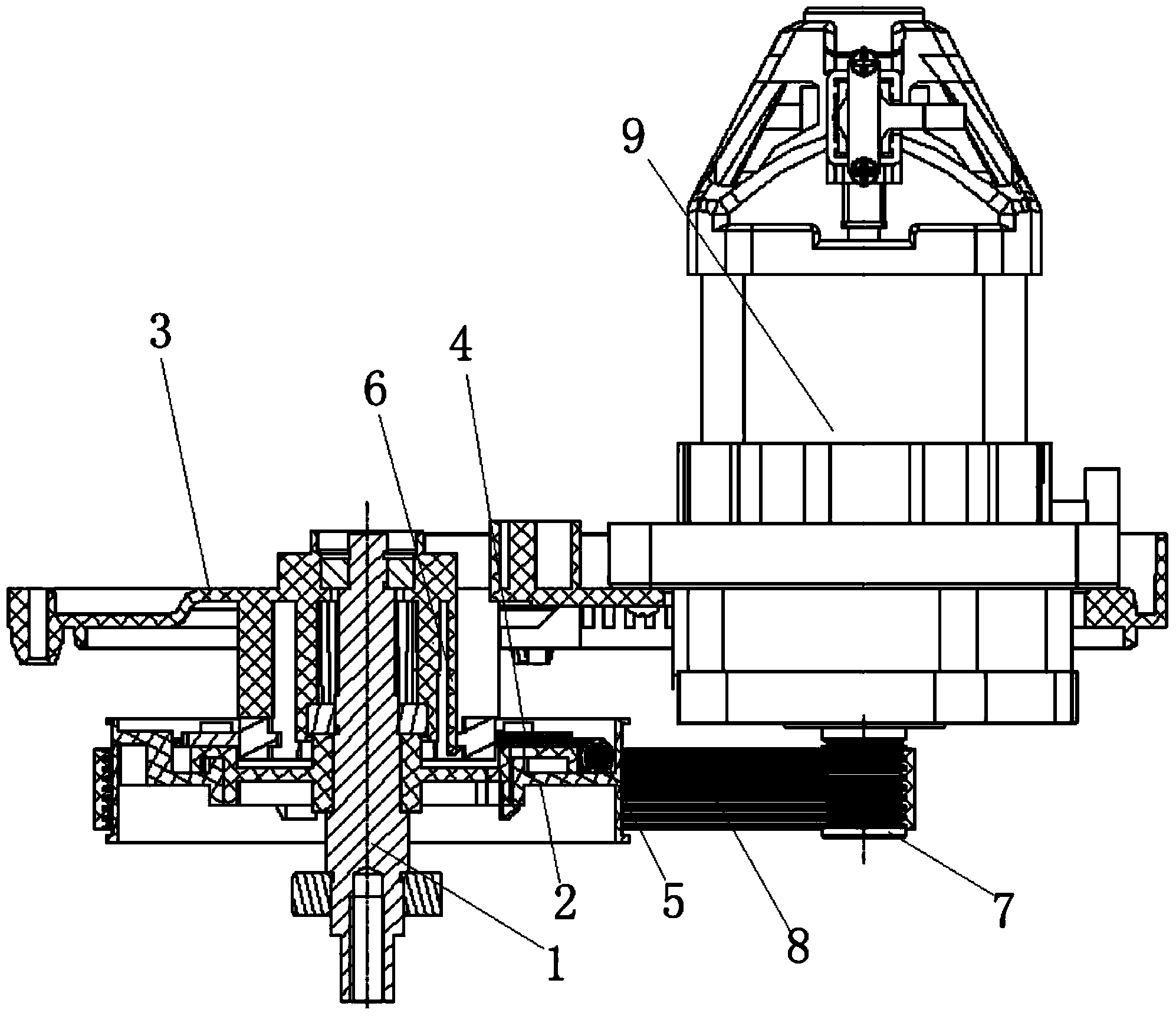
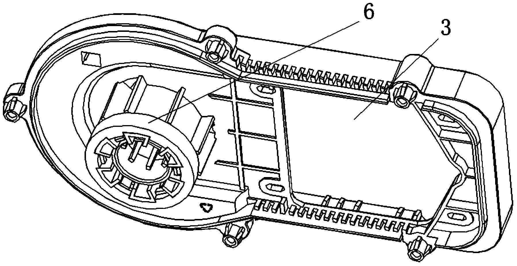
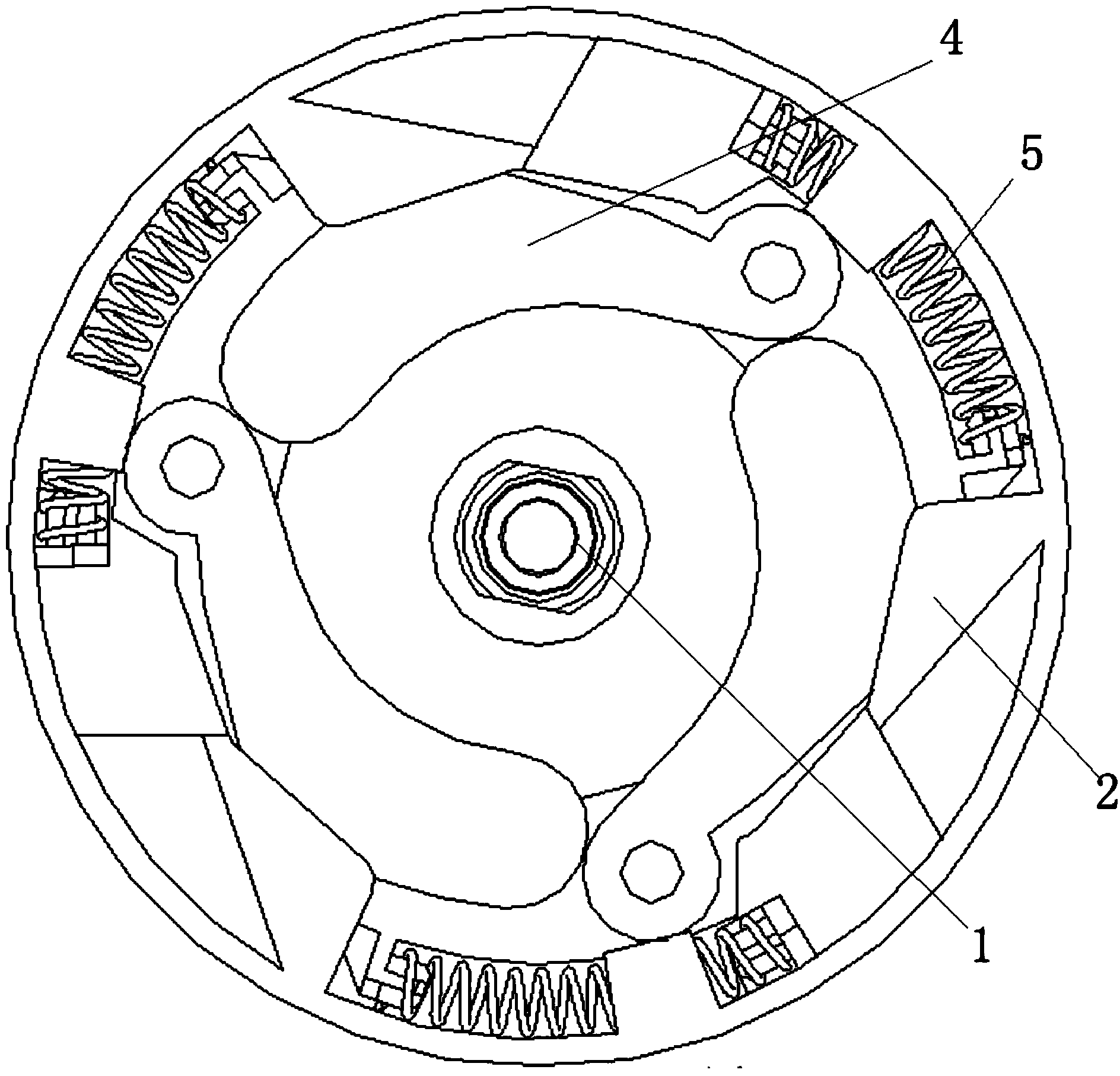
[0015] Figure 1-3 One embodiment of the invention is shown.

[0016] A brake mechanism, including a pulley shaft 1, a large pulley 2 and a bracket 3 equipped with a motor 9, the large pulley 2 is connected to the bracket 3 through the pulley shaft 1 and fixed in the axial direction, and also includes a small pulley 7, a belt 8 , the small pulley 7 is located at the output end of the motor 9 and rotates coaxially and synchronously with the output end of the motor 9, the axis of the large pulley 2 is parallel to the axis of the small pulley 7, and the belt 8 is sleeved on the large pulley 2 and the small pulley 7 The large pulley 2 is linked with the small pulley 7 outside, and the large pulley 2 and the small pulley 7 are connected by the belt 8, and the friction transmission is used to prevent the rigid transmission from causing damage to the parts when braking. The support 3 is provided with a friction member 6, which is a cylindrical friction sleeve, which is fixedly conne...


PUM


Abstract

The invention discloses a brake mechanism, belongs to the field of garden tools, and solves the problem that the brake time of the brake mechanism is instable. The brake mechanism comprises a belt wheel shaft, a big belt wheel and a support with a motor, wherein the big belt wheel is rotationally connected onto the support by the belt wheel and is axially fixed, and the big belt wheel is linked with the output end of the motor; a brake block and a spring are arranged on the big belt wheel, and a friction piece is arranged on the support; the brake block is movably connected with the big belt wheel and can move between positions away from or in contact with the friction piece, and a distance between a contact part of the brake block with the friction piece and the axis of the big belt wheel is greater than a distance between a contact part of the friction piece with the brake block and the axis of the big belt wheel; the spring generates elastic force allowing the brake block to close to the friction piece. The brake mechanism is controlled by the centrifugal force, and the motor rotating speed and the stopping deceleration time are stable, so the braking force generated by the brake block after the motor is stopped and the time required by brake tools are stable, and the braking process is smooth.

Description

technical field [0001] The invention relates to the field of garden tools, in particular to a brake mechanism. Background technique [0002] Due to the requirements of safety braking time, the mechanical brake structure used for braking in motor-driven lawn mowers, rotary tillers or related garden tools in the prior art is not stable enough, and the disadvantages of large fluctuations in braking time cannot be satisfied. its requirements. Contents of the invention [0003] The purpose of the present invention is to provide a braking mechanism capable of smooth braking. [0004] In order to achieve the above object, the present invention adopts the following technical solutions: a brake mechanism, comprising a pulley shaft, a large pulley and a bracket equipped with a motor, the large pulley is connected to the support by rotation of the pulley shaft and fixed in the axial direction, the large pulley and The output end of the motor is linked; there are brake blocks and sp...

Claims


Application Information

Patent Timeline
IPC IPC(8): F16D59/00
CPCA01D34/78F16D59/00
Inventor 张进
Owner ZHEJIANG YAT ELECTRICAL APPLIANCE CO LTD
Why Eureka
Try Eureka